Laser welding Al and Fe members with Zn filler

a technology of fe members and zn filler, which is applied in the direction of manufacturing tools, welding apparatus, transportation and packaging, etc., can solve the problems of serious thermal history and breakage of intermetallic compound layers, and achieve the effect of increasing joint strength and improving joint strength

Inactive Publication Date: 2013-07-23
HONDA MOTOR CO LTD
View PDF38 Cites 3 Cited by
  • Summary
  • Abstract
  • Description
  • Claims
  • Application Information

AI Technical Summary

Benefits of technology

[0008]One or more examples of the present invention provide a method for joining metallic members and a joint structure. The method can improve joint strength between a Fe-based metallic member and an Al-based metallic member by increasing joint strength in the interface parts between the Fe-based metallic member and a joining layer.
[0009]The present inventors made keen investigations to heating technology at the joining of a Fe-based metallic member and an Al-based metallic member using a Zn-based filler metal. In the conventional joining using the Zn-based filler metal, only the Zn-based filler metal was heated so as not to melt the Fe-based metallic member. As a result of investigations to the conventional joining, the present inventors have found that joint strength between the Fe-based metallic member and the joining layer having a Zn-based filler metal can be increased by melting the joined part of the Fe-based metallic member by heating at a temperature higher than a melting point of the Fe-based material.

Problems solved by technology

However, in the case that an intermetallic compound layer formed in the interface part between the Fe-based metallic member and the joining layer is brittle, the breakage may be generated in such the intermetallic compound layer.
Therefore, the problem due to the thermal history was serious.

Method used


Image

  • Laser welding Al and Fe members with Zn filler
  • Laser welding Al and Fe members with Zn filler
  • Laser welding Al and Fe members with Zn filler

Examples


example 1

(1) Example 1

Case using Zn—Al-based Filler Metal

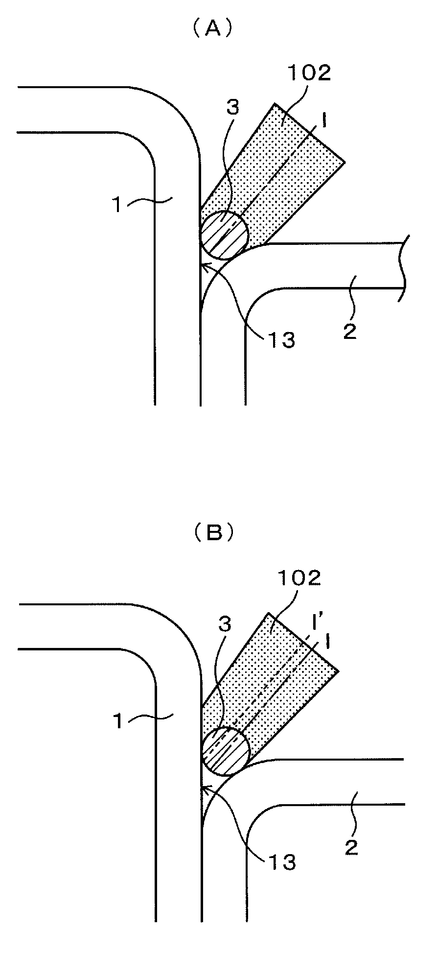
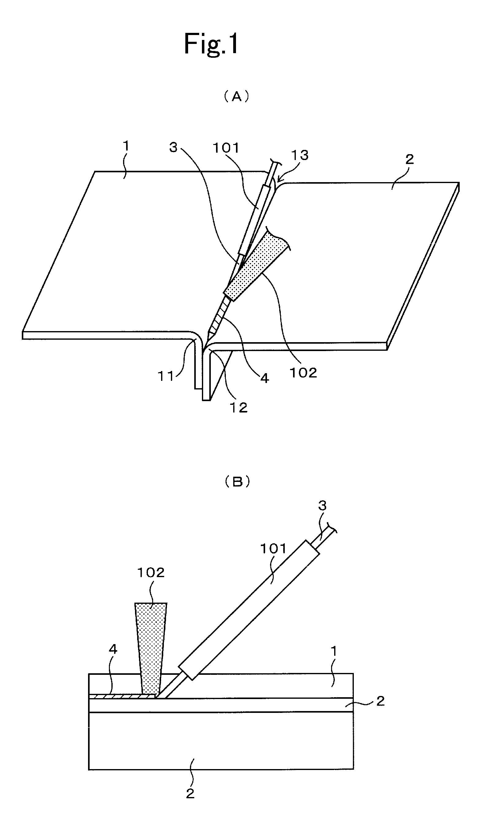
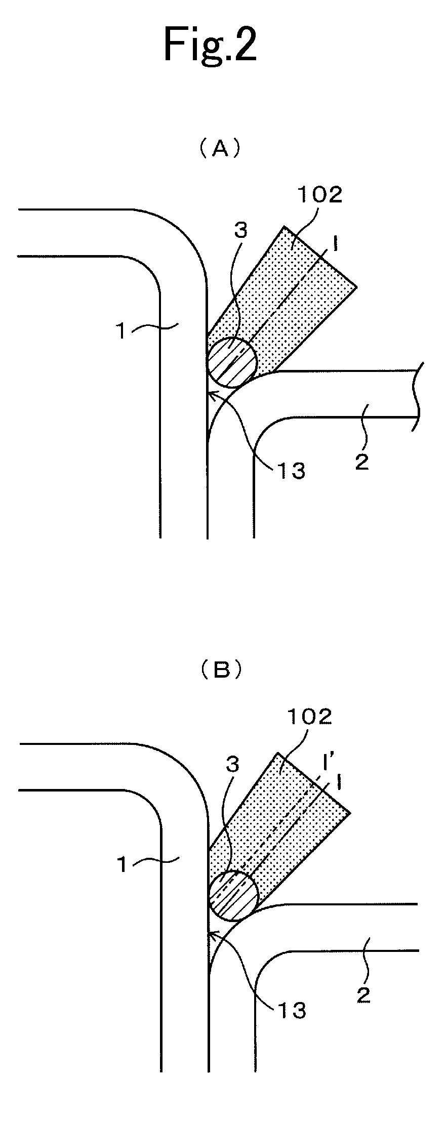
[0145]In Example 1, a Fe-based metallic member and an Al-based metallic member were arranged in the same arrangement embodiment shown in FIG. 19(A), and a groove shape was formed by curved portions of those metallic members. A wire-shaped Zn—Al-based filler metal was fed to a central portion of the groove shape through a wire guide, and while feeding, a tip portion of the Zn—Al-based grazing filler member was irradiated with laser beam. Thus, a flare joint-shaped joined structure of metallic members was produced.

[0146]Regarding joining conditions, a size of two metallic members had a length in a horizontal direction of 82 mm in FIG. 19(A) and a length in a longitudinal direction of 200 mm in FIG. 19(A), and a height of stepped portion in the joined part of two metallic members was 5 mm. A filler metal having a composition ratio (wt %) of Zn:Al=96:4 was used as a Zn—Al-based filler member. Ar gas was used as a shielding gas, and its fee...

example 2

(2) Example 2

Case using Zn—Si-based Filler Metal

[0153]In Example 2, a flare joint-shaped joined structure of metallic members was produced in the same manner as in Example 1, except for using a Zn—Si-based filler metal as a Zn-based filler metal. Joining conditions were that a light collection diameter of laser beam is 1.8 mm, a laser output is 1.4 kV, a joining speed is 1 m / min, and a wire speed is 3.2 m / min. Appropriate heat input conditions in which the joined part of the Fe-based metallic member is melted by appropriately heating in the formation of a key hole were employed. A steel plate (JAC270, plate thickness: 1.0 mm, length in longitudinal direction in FIG. 19(A): 200 mm, length in horizontal direction in FIG. 19(A): 80 mm) was used as the Fe-based metallic member, and an Al plate (A6K21-T14, plate thickness: 1.0 mm, length in longitudinal direction in FIG. 19(A): 200 mm, length in horizontal direction in FIG. 19(A): 80 mm) was used as the Al-based metallic member.

[0154]In ...


PUM

PropertyMeasurementUnit
melting pointaaaaaaaaaa
heightaaaaaaaaaa
heightaaaaaaaaaa

Abstract

In joining an Fe-based metallic member comprising an Fe-based material and an Al-based metallic member comprising an Al-based material by a Zn-based filler metal, a joined part of the Fe-based metallic member is heated at a temperature higher than a melting point of the Fe-based material.

Description

TECHNICAL FIELD[0001]The present invention relates to a method for joining a Fe-based metallic member and an Al-based metallic member by interposing a filler metal between the Fe-based metallic member and the Al-based metallic member, a joint structure, and a filler metal.BACKGROUND ART[0002]Joint structure of metallic members, such as various joints, is produced by joining dissimilar metallic members. In the joining of dissimilar metallic members, brazing is conducted by irradiating a brazing filler metal interposed between those dissimilar metallic members with laser beam, and heating the brazing filler metal. A joining layer is formed thereby between the dissimilar metallic members. Thus, a joint structure of metallic members is produced.[0003]For example, in the case of using a Fe-based metallic member containing a Fe-based material and an Al-based metallic member containing an Al-based material as dissimilar metallic members, Al and Zn do not form a compound layer and forms an ...

Claims


Application Information

Patent Timeline
Patent Type & Authority Patents(United States)
IPC IPC(8): B23K26/00B23K35/12B23K1/19
CPCB23K1/14B23K1/19B23K26/24B23K35/28B23K1/0056B23K35/3053B32B15/01Y10T428/12757Y10T428/12736B23K2203/20B23K2103/20B23K35/282
Inventor WAKISAKA, TAISEIOKUMURA, TOKUJISUZUKI, TAKANORI
Owner HONDA MOTOR CO LTD
Why Eureka
Try Eureka