Optical module for increasing magnification of microscope

a technology of optical modules and microscopes, applied in the field of optical microscopes, can solve the problems of prism use, optical microscope art, etc., and achieve the effects of increasing the effective length of the microscope, increasing the magnification of the microscope, and increasing the magnification of the optical microscop

Inactive Publication Date: 2013-07-23
EMC2 FAMILY TRUST
View PDF10 Cites 0 Cited by
  • Summary
  • Abstract
  • Description
  • Claims
  • Application Information

AI Technical Summary

Benefits of technology

[0011]It is another object to provide a system, inclusive of such a module which, by folding of the optical path, increases the effective length thereof and, with it, the magnification of the microscope.
[0012]It is a still further object of the invention to provide a method of increasing magnification of an optical microscope by providing a plurality of orthonormal reflective elements, in the nature of prisms, between the objective and the eyepiece of the microscope, to effectively fold and, thereby, increase the optical path between the objective and the eyepiece of the system.

Problems solved by technology

The prior art in the area of optical microscopes that entails the use of prisms as reflectors to achieve an enhanced capability are, on the one hand, limited to systems seeking to create a dual objective as, for example, to view a specimen at either two different magnifications or from two different directions at the same time, and other hand, microscopes seeking to achieve a stereoscopic effect at the eyepiece thereof, that is, a three-dimensional viewing of a specimen.

Method used


Image

  • Optical module for increasing magnification of microscope
  • Optical module for increasing magnification of microscope
  • Optical module for increasing magnification of microscope

Examples


Embodiment Construction

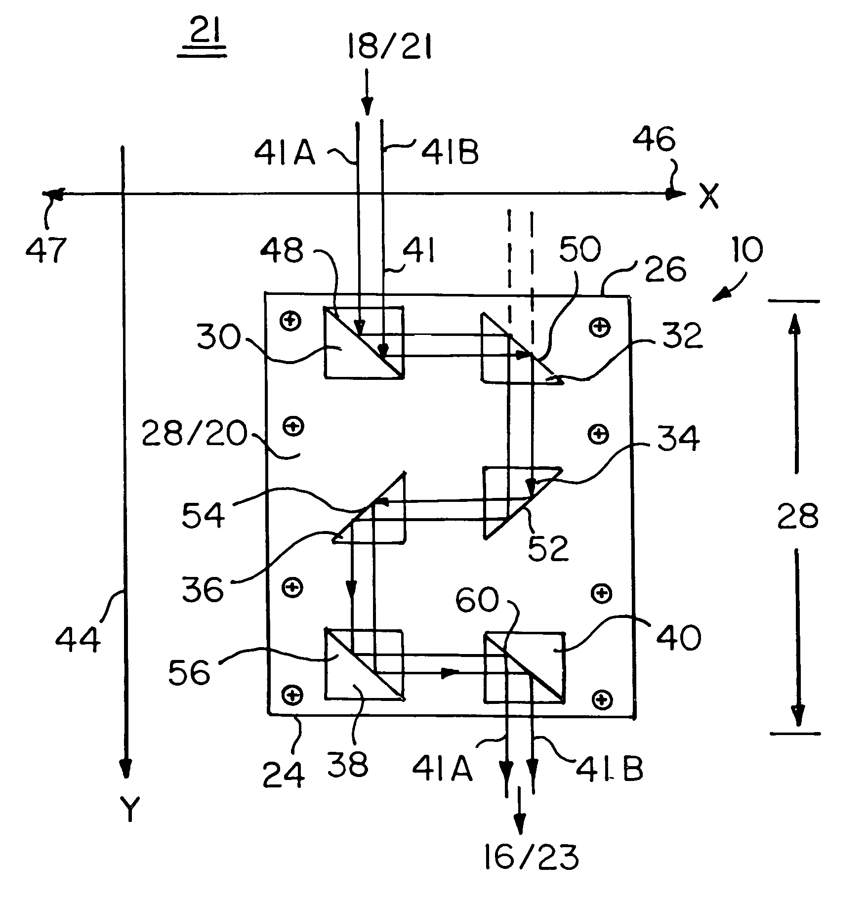
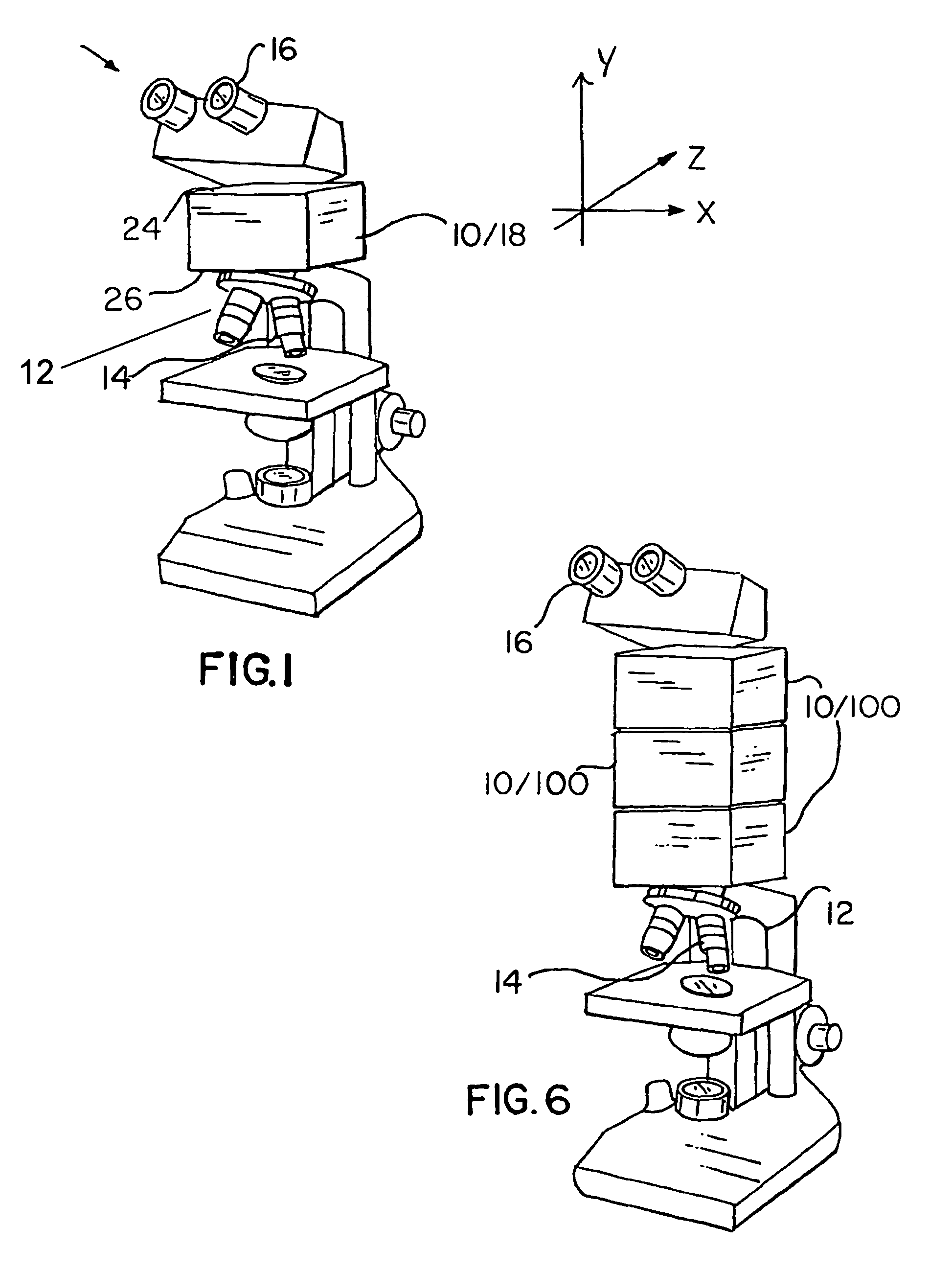
[0020]As shown in FIG. 1, an optical module 10 can be inserted into a microscope 12, or similar optical magnification system, to enhance its magnification. The microscope 12 shown in FIG. 1 comprises a standard light microscope having, e.g., between about 1000× and 4000× magnification. As is conventional, said microscope 12 comprises an objective 14, an eyepiece 16, and an optical path 18 extending therebetween. This optical path has a standard length of between about 160 to 190 millimeters (mm), conventionally referred to as the tube length. The optical module 10 is inserted between the objective 14 and eyepiece 16. An X, Y, Z coordinate which is also shown in FIG. 1.

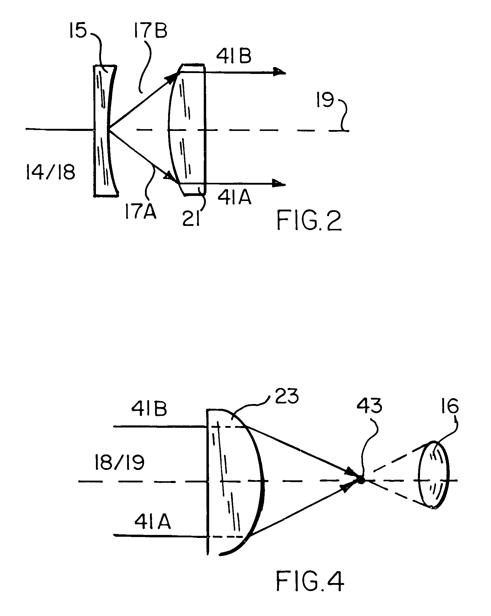
[0021]Shown in FIG. 2 is the optical path 18 from objective 14 and the beam separation or divergence strategy provided to provide input beams 41A and 41B to the optical module 10, below described. More particularly, light from objective 14 is provided along optical path 18 and axis 19 to a plano-concave lens 15 or equi...


PUM


Abstract

An optical module for increasing magnification of a microscope includes an objective and an eyepiece between which is an optical path for light to travel. The optical includes light diverging elements for dividing the optical path into two parallel light paths after leaving the objective; and several orthonormally-arranged reflective elements including at least a first and a last reflective element, each reflective element having a reflective surface diagonal relative to the orthonormal arrangement of the elements, and also arranged to successively reflect the parallel light paths, from element to element, from the objective when the module is inserted in the optical microscope, beneath the eyepiece. Also included are light converging elements for converging the parallel paths into a single path before producing an image at the eyepiece.

Description

BACKGROUND OF THE INVENTION[0001]1. Field of the Invention[0002]The present invention relates to the field of optical microscopy, and more specifically to an apparatus for enhancing magnification.[0003]2. Prior Art[0004]The prior art in the area of optical microscopes that entails the use of prisms as reflectors to achieve an enhanced capability are, on the one hand, limited to systems seeking to create a dual objective as, for example, to view a specimen at either two different magnifications or from two different directions at the same time, and other hand, microscopes seeking to achieve a stereoscopic effect at the eyepiece thereof, that is, a three-dimensional viewing of a specimen. The prior art which reflects one or more of these goals is represented by U.S. Pat. No. 5,146,363 (1992) to Nagano; U.S. Pat. No. 5,701,198 (1997) to Schoppe; U.S. Pat. No. 5,764,408 (1998) to Otaki; and U.S. Pat. No. 6,134,01 (2000) to Zavislan.[0005]The present invention is also an improvement of t...

Claims


Application Information

Patent Timeline
Patent Type & Authority Patents(United States)
IPC IPC(8): G02B21/00
CPCG02B21/24
Inventor WEINSTOCK, RONALD J.
Owner EMC2 FAMILY TRUST
Why Eureka
Try Eureka