
Dynamic physical memory replacement through address swapping

a dynamic physical memory and address swapping technology, applied in the direction of memory adressing/allocation/relocation, redundant hardware error correction, instruments, etc., can solve the problems of increasing the cost of memory manufacturers, reducing the yield of working drams/dimms, and general bad drams of the entire dram devi

Inactive Publication Date: 2013-07-23
INTEL CORP
View PDF6 Cites 6 Cited by
  • Summary
  • Abstract
  • Description
  • Claims
  • Application Information

AI Technical Summary

Benefits of technology

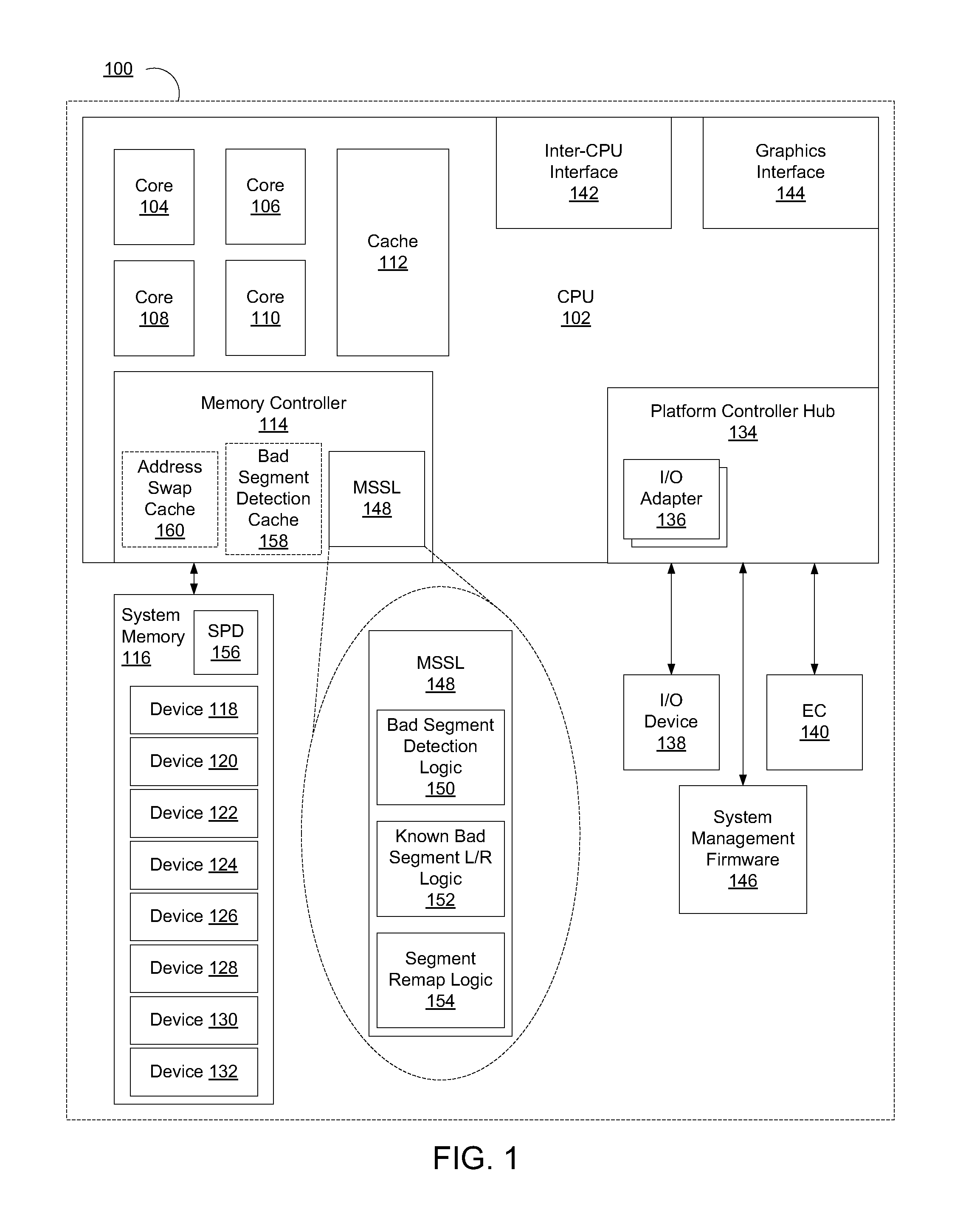
The invention relates to replacing bad portions of system memory with spare good portions through address swapping. The technical effect of the invention is to improve the yield of working memory modules, decrease the cost of manufacturing, and increase the speed of manufacturing for OEMs. Additionally, the invention allows for the dynamic swapping of memory segments, which can be useful in detecting and replacing failed memory segments. This helps to prolong the life of memory devices and improve overall performance.

Problems solved by technology

When portions of a dynamic random access memory (DRAM) device in a dual in-line memory module (DIMM) fail, the entire DRAM device is generally considered a bad DRAM or in a worst case scenario the DIMM is considered a bad DIMM.
Considering entire DRAM devices or entire DIMMs bad because a portion of a DRAM device has failed reduces the yield of working DRAMs / DIMMs for memory manufacturers, increases their cost, and lengthens the manufacturing time for Original Equipment Manufacturers (OEMs) since replacement DIMMs must be handled and retested prior to shipping the product.
Additionally, portions of a DRAM device may also fail during the lifetime of the device, even when the device comes off the manufacturing line in perfect working condition.
This is due to normal wear and tear that takes place over a lifetime of usage of the device.
These failures generally happen once the DRAM / DIMM is in the use of an end user / customer and will cause the person to replace the entire DIMM when a majority of the memory in the DIMM may still be working properly.

Method used


Image

  • Dynamic physical memory replacement through address swapping
  • Dynamic physical memory replacement through address swapping
  • Dynamic physical memory replacement through address swapping

Examples


Embodiment Construction

[0013]Elements of an apparatus, system, method, and machine-readable medium to implement swapping of physical memory segments are disclosed.

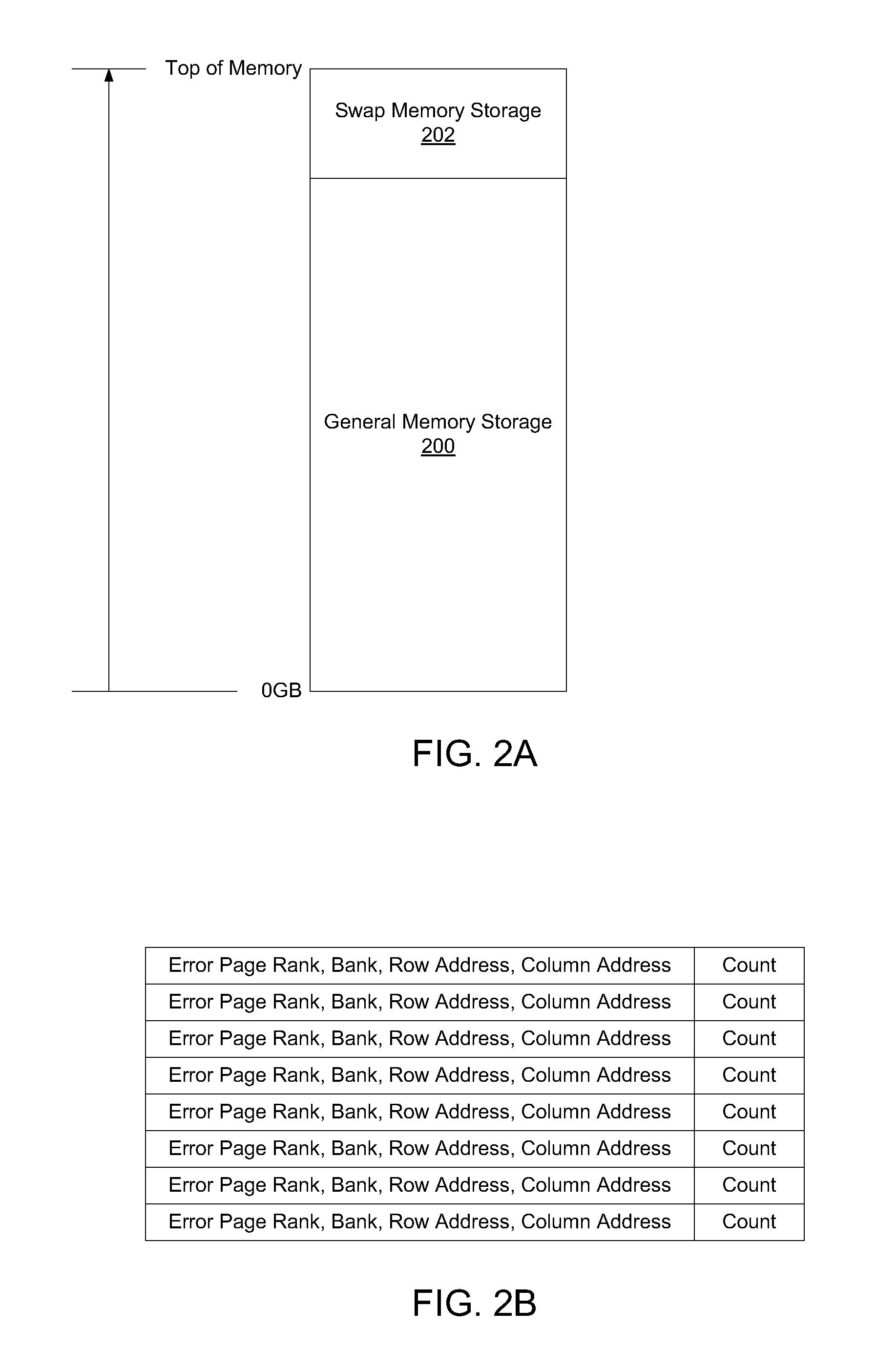
[0014]There are references throughout this document to the term memory “segment.” A segment of memory is meant to convey a generic portion of memory. In different embodiments, a segment could mean a portion of memory as small as one stored bit of information or it could mean a portion of memory that takes up more than an entire device of memory. Though, generally, a segment of memory may convey a cacheline of memory or a physical page of memory in many embodiments. Cachelines vary in size based upon the specific implementation per processor but generally range from 8 to 1024 bytes in current solutions. A physical memory page also may vary in size. For example, a common size memory page may be 4 Kilobytes.

[0015]A memory segment in a memory device may fail for a number of reasons including imperfections in the manufacturing process to normal wear ...


PUM


Abstract

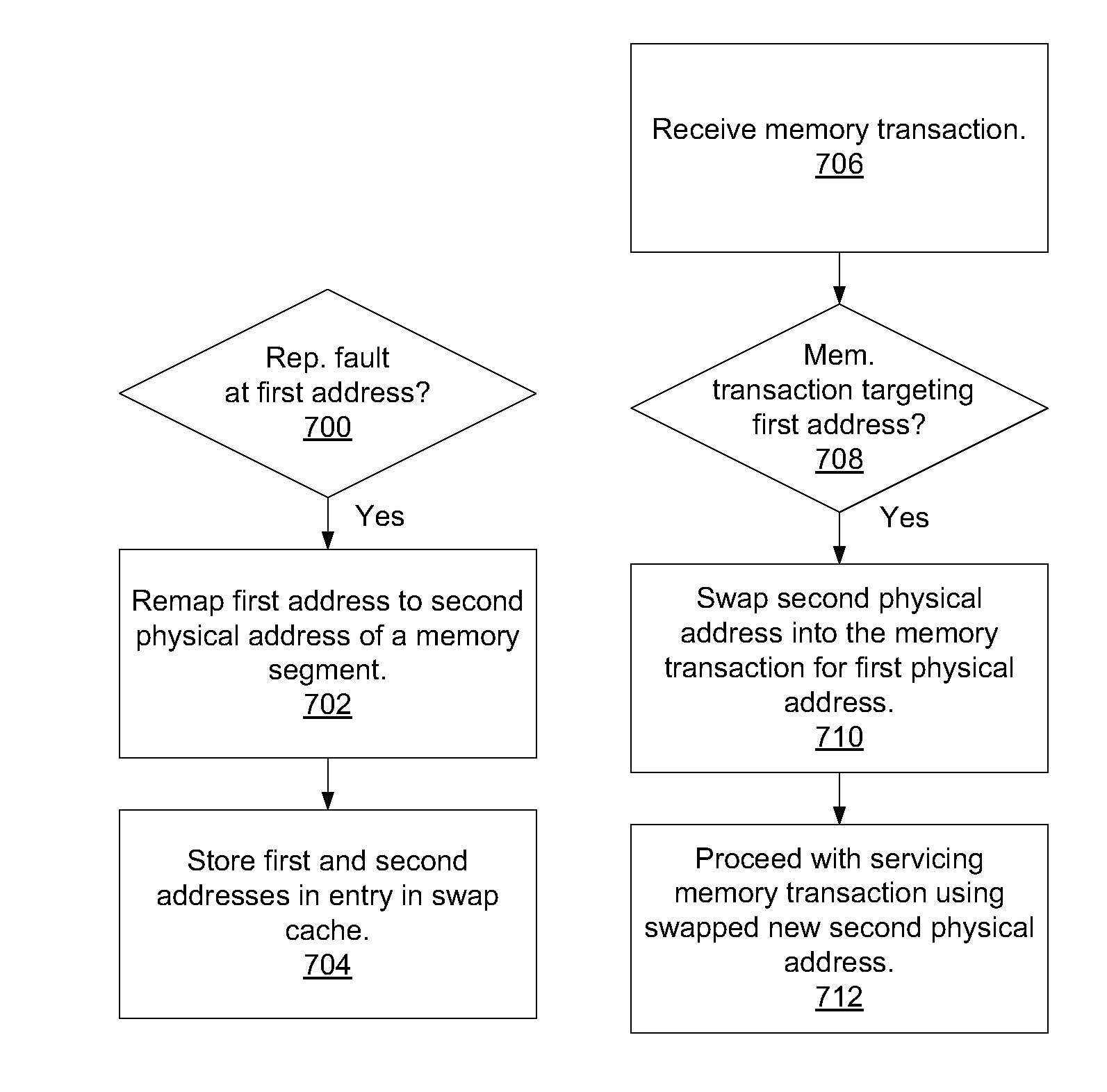
An apparatus, system, method, and machine-readable medium are disclosed. In one embodiment the apparatus includes an address swap cache. The apparatus also includes memory segment swap logic that is capable of detecting a reproducible fault at a first address targeting a memory segment. Once detected, the logic remaps the first address targeting the faulty memory segment with a second address targeting another memory segment. The logic stores the two addresses in an entry in the address swap cache. Then the memory segment swap logic receives a memory transaction that is targeting the first physical address and use the address to perform a lookup process in the address swap cache to determine if an entry exists that has the faulty address. If an entry does exist for that address, the logic then swaps the second address into the memory transaction for the first address.

Description

FIELD OF THE INVENTION[0001]The invention relates to replacing bad portions of system memory out with spare good portions of system memory through address swaps.BACKGROUND OF THE INVENTION[0002]When portions of a dynamic random access memory (DRAM) device in a dual in-line memory module (DIMM) fail, the entire DRAM device is generally considered a bad DRAM or in a worst case scenario the DIMM is considered a bad DIMM. Considering entire DRAM devices or entire DIMMs bad because a portion of a DRAM device has failed reduces the yield of working DRAMs / DIMMs for memory manufacturers, increases their cost, and lengthens the manufacturing time for Original Equipment Manufacturers (OEMs) since replacement DIMMs must be handled and retested prior to shipping the product. Additionally, portions of a DRAM device may also fail during the lifetime of the device, even when the device comes off the manufacturing line in perfect working condition. This is due to normal wear and tear that takes pla...

Claims


Application Information

Patent Timeline
Patent Type & Authority Patents(United States)
IPC IPC(8): G11C29/00
CPCG06F11/1666G11C29/76G06F11/20G06F12/02G06F12/08G06F13/1642
Inventor MORRIS, TONIA G.BLANKENBECKLER, LAWRENCE D.
Owner INTEL CORP
Learn More