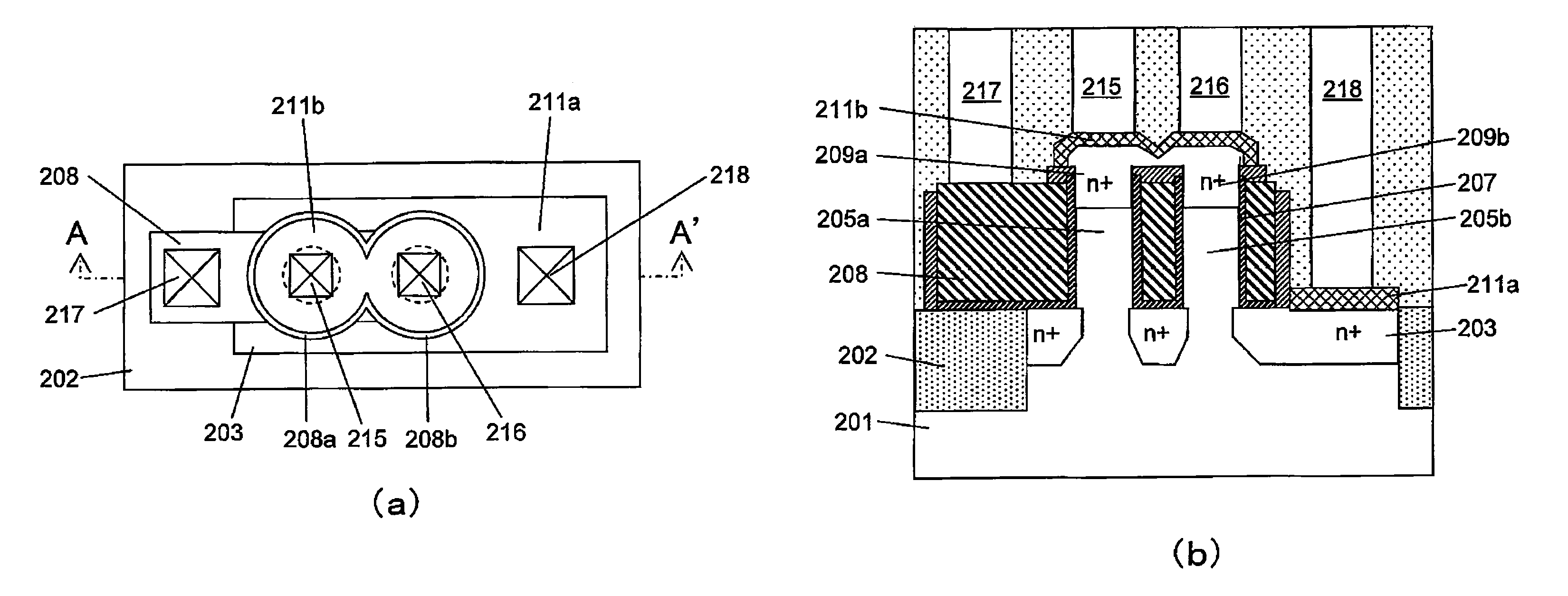
Semiconductor device including a MOS transistor and production method therefor
a technology of mos transistor and semiconductor device, which is applied in the direction of semiconductor device, basic electric element, electrical apparatus, etc., can solve the problems of reducing the size of the device, increasing the probability of short circuit between the gate and the contact, and difficulty in forming an adequate silicide on the top of the pillar, so as to reduce the narrow width effect, improve the transistor characteristics, and reduce the resistance of the interface
- Summary
- Abstract
- Description
- Claims
- Application Information
AI Technical Summary
Benefits of technology
Problems solved by technology
Method used
Image
Examples
first embodiment
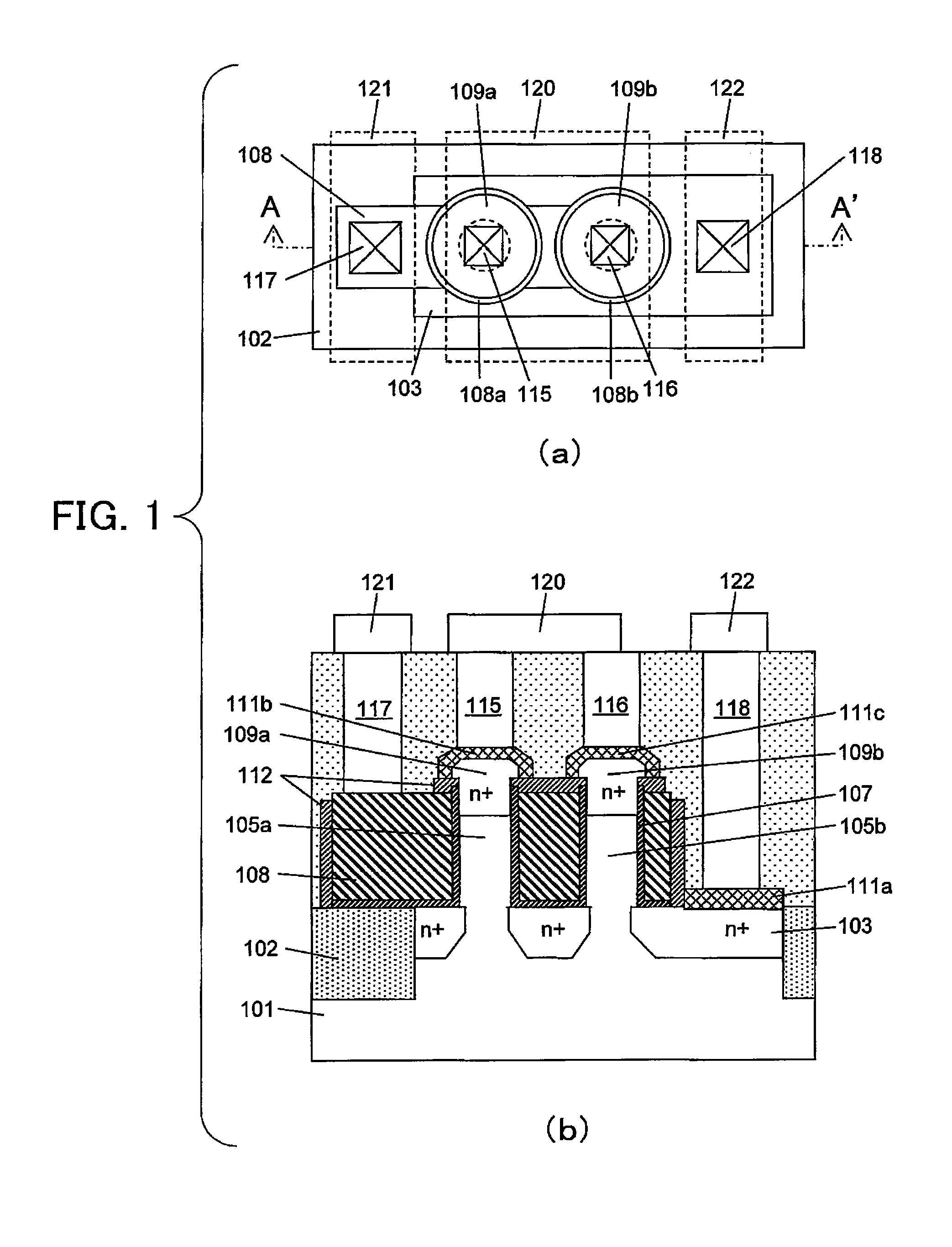
[0080]FIG. 1(a) is a top plan view showing a transistor according to a first embodiment of the present invention, and FIG. 1(b) is a sectional view taken along the line A-A′ in FIG. 1(a). With reference to FIGS. 1(a) and 1(b), a structure of the transistor according to the first embodiment will be described below.
[0081]A silicon substrate 101 is isolated on an element-by-element basis by an element isolation region 102, and two pillar-shaped silicon layers (pillar-shaped semiconductor layers) 105a, 105b are formed on the silicon substrate. A gate dielectric film (first dielectric film) 107 and a gate electrode (108a, 108b) are formed around each of the pillar-shaped silicon layers (pillar-shaped semiconductor layers). In the first embodiment, a High-k film is used as the gate dielectric film (first dielectric film), and a metal film is used as the gate electrode. Alternatively, a silicon oxynitride film formed by oxidation may be used as the gate dielectric film (first dielectric fi...
second embodiment
[0103]A second embodiment shows one example where the present invention is applied to a transistor formed by connecting in series two transistors. FIG. 21(a) is a top plan view showing a transistor according to the second embodiment, and FIG. 21(b) is a sectional view taken along the line A-A′ in FIG. 21(a). With reference to FIGS. 21(a) and 21(b), a structure of the transistor according to the second embodiment will be described below. A silicon substrate 601 is isolated on an element-by-element basis by an element isolation 602. Two pillar-shaped silicon layers (pillar-shaped semiconductor layers) 605a, 605b constituting a first transistor, and two pillar-shaped silicon layers (pillar-shaped semiconductor layers) 605c, 605d constituting a second transistor, are formed on the silicon substrate. A gate dielectric film (first dielectric film) 607 and a gate electrode (609a to 609d) are formed around each of the pillar-shaped silicon layers (pillar-shaped semiconductor layers). In the...
third embodiment
[0108]A third embodiment shows one example where the present invention is applied to a CMOS inverter. FIG. 23(a) is a top plan view showing a CMOS inverter according to the third embodiment, and FIG. 23(b) is a sectional view taken along the line A-A′ in FIG. 23(a). In FIGS. 23(a) and 23(b), an interconnection layer 820a connected to an NMOS transistor is connected to GND, and an interconnection layer 820b connected to a PMOS transistor is connected to Vcc. An input signal Vin is input into a gate interconnection layer 808 from an interconnection layer 822, and two interconnection lines 821a, 821b connected from respective upper sides of the NMOS and PMOS transistors are connected to each other through an interconnection layer to output an output signal Vout therefrom. In this manner, a CMOS inverter is formed.
[0109]With reference to FIGS. 23(a) and 23(b), a structure of the CMOS inverter according to the third embodiment will be described below. A silicon substrate 801 is isolated ...
PUM
 Abstract
Description
Claims
Application Information
 - R&D
- Intellectual Property
- Life Sciences
- Materials
- Tech Scout
- Unparalleled Data Quality
- Higher Quality Content
- 60% Fewer Hallucinations
Browse by: Latest US Patents, China's latest patents, Technical Efficacy Thesaurus, Application Domain, Technology Topic, Popular Technical Reports.
© 2025 PatSnap. All rights reserved.Legal|Privacy policy|Modern Slavery Act Transparency Statement|Sitemap|About US| Contact US: help@patsnap.com


