Terminal system for planar magnetics assembly

a planar magnetic and terminal system technology, applied in the direction of transformer/inductance details, basic electric elements, inductances, etc., can solve the problems of additional electromagnetic interference, power loss, and can be difficult to reduce, and the conductors do not solve the problem, etc., to reduce the ac resistance, increase efficiency, and reduce the ac and dc resistance of the interface

Active Publication Date: 2008-12-02
STANDEX ELECTRONICS
View PDF10 Cites 25 Cited by
  • Summary
  • Abstract
  • Description
  • Claims
  • Application Information

AI Technical Summary

Benefits of technology

[0012]The terminal system of the present invention provides a totally flexible paralleling of any combination of leadframes in the same way as a single L-shaped terminal, but it brings the screw-type interface point to the middle of planar transformer. In such construction, AC current in the leadframes tends to flow symmetrically from both halves of the planar stack. The currents in the leadframes do not vary as much, therefore reducing AC resistance and increasing efficiency. Compared to a single L-shaped terminal, a double terminal system provides twice the cross-sectional copper area for conduction given the same terminal thickness, thus the AC and DC resistance of the interface is reduced, and efficiency is further increased. The assembly process of the present invention is also improved over the prior art since soldering of the double terminal system to corresponding leadframes is easier. Still further, the present invention also reduces overall converter height because relevant screws, washers, and nuts are not shifted to either the top or bottom of the planar transformer, as is the case with a single L-shaped terminal.

Problems solved by technology

The impedance of this connection generates power losses, additional electromagnetic interference and can be difficult to reduce.
However, even flat planar conductors do not solve the problem of sufficient copper cross-sectional area for heavy current windings.
In many applications paralleling just two leadframes does not yield low enough winding resistance.
Swaging may put part of the standoff above the surface of the planar leadframe thus making electrical connection between the two flat surfaces questionable.
Second, in many cases transformers are custom designed to meet specific requirements.
Therefore, the distance between leadframes varies widely from model to model so that it becomes impractical to design and manufacture different height standoffs for every model.
Third, connecting three or more leadframes in parallel using standoffs, while possible, presents a difficult manufacturing problem.
However, there are two major problems with this approach.
Increasing the L-shaped terminal's thickness will not solve the problem in an optimum way due to the skin effect.
Second, soldering a very thick copper L-shaped terminal to multiple leadframes becomes a difficult manufacturing task due to the heat-sink effect of massive copper on the soldering joint.
An additional problem occurs for both standoff and single L-shaped terminals.
This phenomena will increase AC resistance and, therefore, reduce efficiency.

Method used


Image

  • Terminal system for planar magnetics assembly
  • Terminal system for planar magnetics assembly
  • Terminal system for planar magnetics assembly

Examples


Embodiment Construction

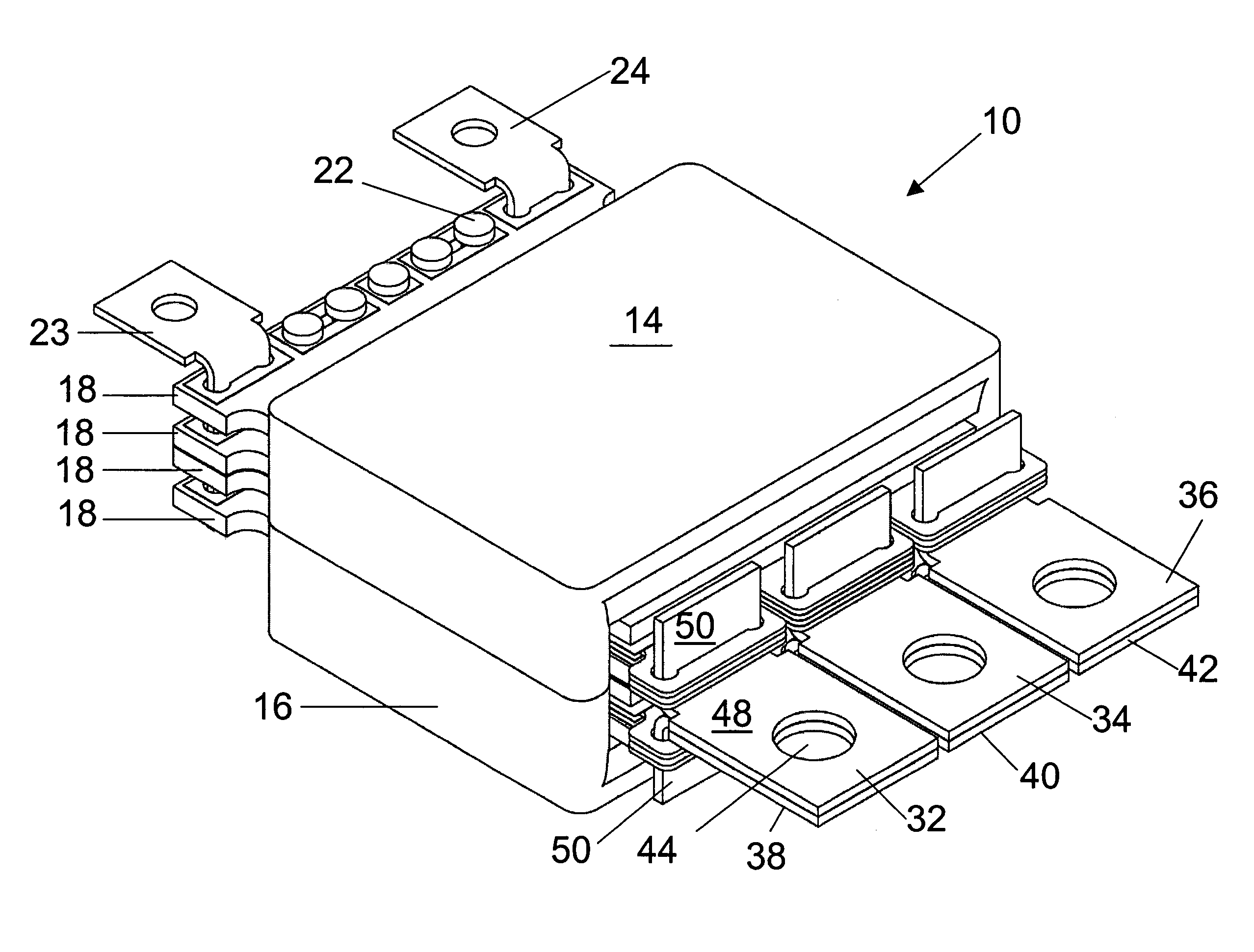
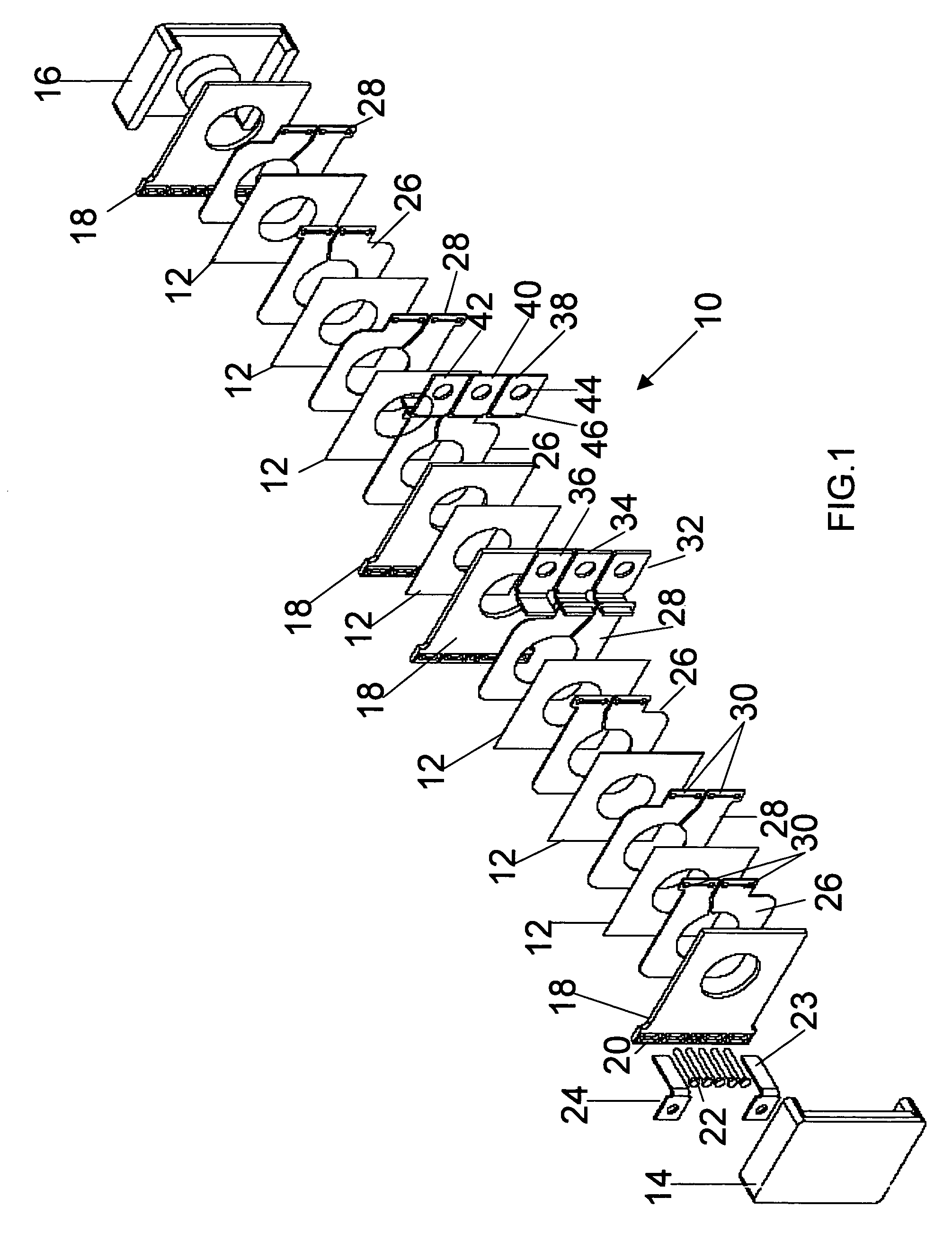
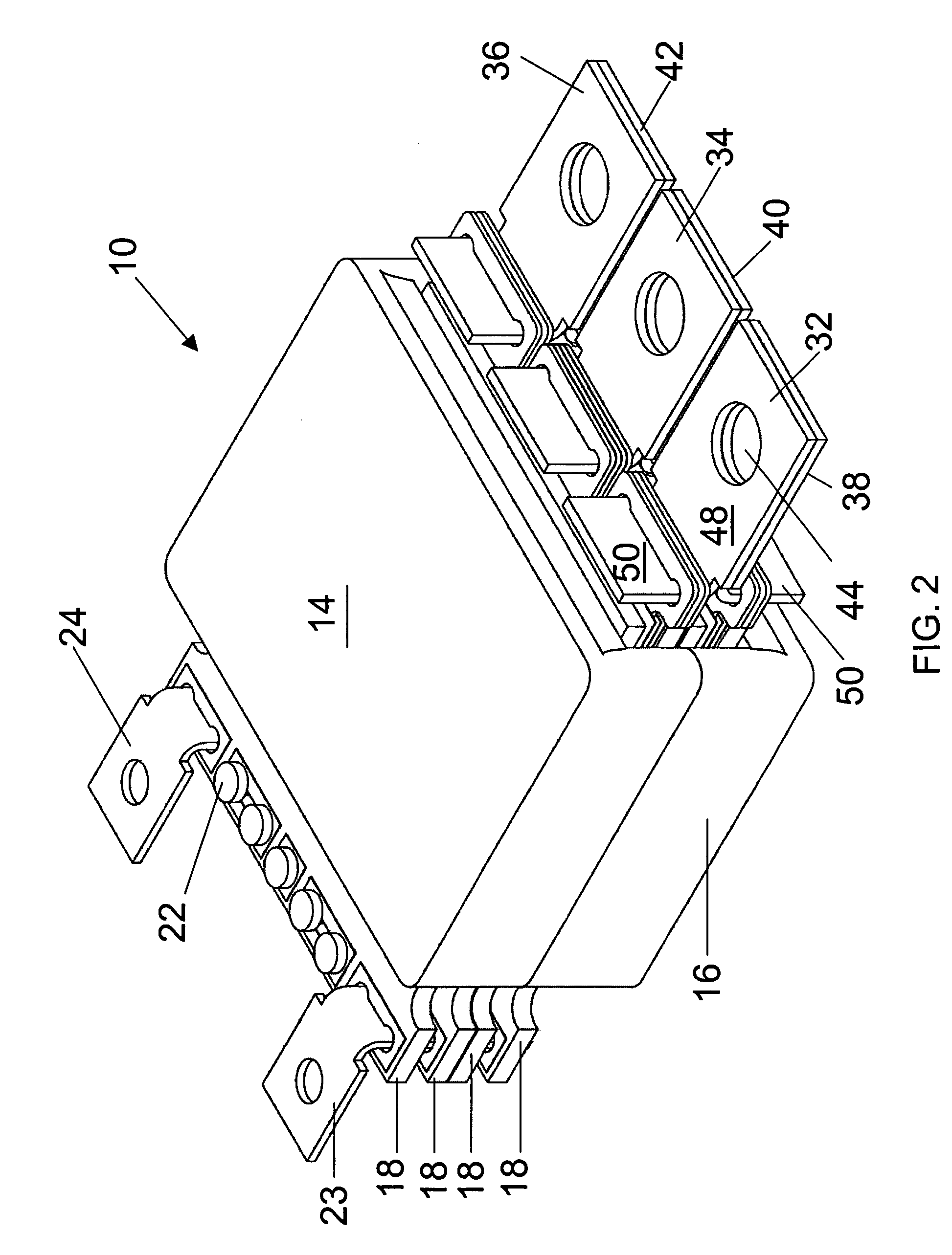
[0018]Referring to FIGS. 1 and 2, a planar transformer 10 utilizing the present invention is shown; however, it should be understood that planar transformer is merely exemplary and could have other configurations or could be a planar inductor rather than a planar transformer. Planar transformer 10 has a plurality of thin dielectric insulators 12 with a plurality of planar primary windings 18 and a plurality of planar secondary windings 26 and 28 positioned between insulators 12. Primary windings 18 have a plurality of apertures 20 through which pins 22 and L-shaped terminals 23 and 24 are positioned. L-shaped terminals 23 and 24 are positioned through each of planar primary windings 18. Planar transformer 10 has a plurality of terminals 32, 34, 36, 38, 40, and 42 that are L-shaped having two legs 48 and 50 that are approximately 90° apart with an aperture 44 through flat surface 46 on leg 48. Legs 50 of L-shaped terminals 32-42 are positioned through apertures 30 in secondary windin...


PUM

PropertyMeasurementUnit
AC currentaaaaaaaaaa
thicknessaaaaaaaaaa
thicknessaaaaaaaaaa

Abstract

A planar magnetic device comprising a planar core, a first plurality of planar windings having apertures, a second plurality of planar windings having apertures, a planar core surrounding at least a portion of the first and second plurality of planar windings, a first terminal having first and second legs separated by about ninety degrees, and a second terminal having first and second legs separated by about ninety degrees, wherein the first leg of the first terminal is positioned through the apertures in the first plurality of planar windings, the first leg of the second terminal is positioned through the apertures in the second plurality of planar windings such that the second leg of the first terminal is adjacent the second leg of the second terminal.

Description

STATEMENT REGARDING FEDERALLY SPONSORED RESEARCH OR DEVELOPMENT[0001]N / ACROSS-REFERENCE TO RELATED APPLICATION[0002]N / AFIELD OF THE INVENTION[0003]This invention relates generally to planar magnetic assemblies, and more particularly, to an improved terminal system for planar magnetic assemblies.BACKGROUND OF THE INVENTION[0004]Planar magnetic assemblies, i.e., transformers and inductors, are used widely in high current / low voltage switching power supplies operating from 40 kHz to 1 MHz. A typical transformer is a major part of the power converter, which either steps voltage up or down depending on the application. In higher power converters either the primary winding or the secondary winding of the transformer has to carry AC current over 100 amperes RMS and sometimes up to 500 amperes RMS or more. Filter inductors, on the other hand, have to carry DC current, but the values can also be quite high. In both cases, the planar magnetic assembly has to be connected to semiconductors, wh...

Claims


Application Information

Patent Timeline
Patent Type & Authority Patents(United States)
IPC IPC(8): H01F5/00
CPCH01F27/2804H01F27/2847H01F27/29H01F17/0013H01F27/2852
Inventor ESTROV, ALEXANDER
Owner STANDEX ELECTRONICS
Why Eureka
Try Eureka