Power generating apparatus of renewable energy type and method for installing hydraulic pump

a technology of renewable energy and power generating equipment, applied in the direction of positive displacement liquid engine, electric generator control, piston pump, etc., can solve the problems of increasing the cost of step-up gear and becoming heavier, and achieve the effect of facilitating the fixing structure, and reducing the cost of installation

Inactive Publication Date: 2013-07-30
MITSUBISHI HEAVY IND LTD
View PDF24 Cites 2 Cited by
  • Summary
  • Abstract
  • Description
  • Claims
  • Application Information

AI Technical Summary

Benefits of technology

[0051]According to the present invention, when the main shaft has a large diameter, it is possible to structure the fixing structure with ease and at low cost, that is capable of transmitting large torque to the hydraulic pump.

Problems solved by technology

To improve power generation efficiency, the power generating apparatus of renewable energy type becomes larger to improve power generation efficiency and the step-up gear becomes heavier and more expensive as well.

Method used


Image

  • Power generating apparatus of renewable energy type and method for installing hydraulic pump
  • Power generating apparatus of renewable energy type and method for installing hydraulic pump
  • Power generating apparatus of renewable energy type and method for installing hydraulic pump

Examples


Embodiment Construction

[0070]A preferred embodiment of the wind turbine generator in relation to the present invention will now be described in detail with reference to the accompanying drawings. The explanations below are made in the case where the preferred embodiments are applied to the wind turbine generator. However, this should not limit the scope of the present invention and the present invention is also applicable to a hydraulic power generator.

[0071]It is intended that unless particularly specified, dimensions, materials, shape, its relative positions and the like shall be interpreted as illustrative only and not limitative of the scope of the present invention.

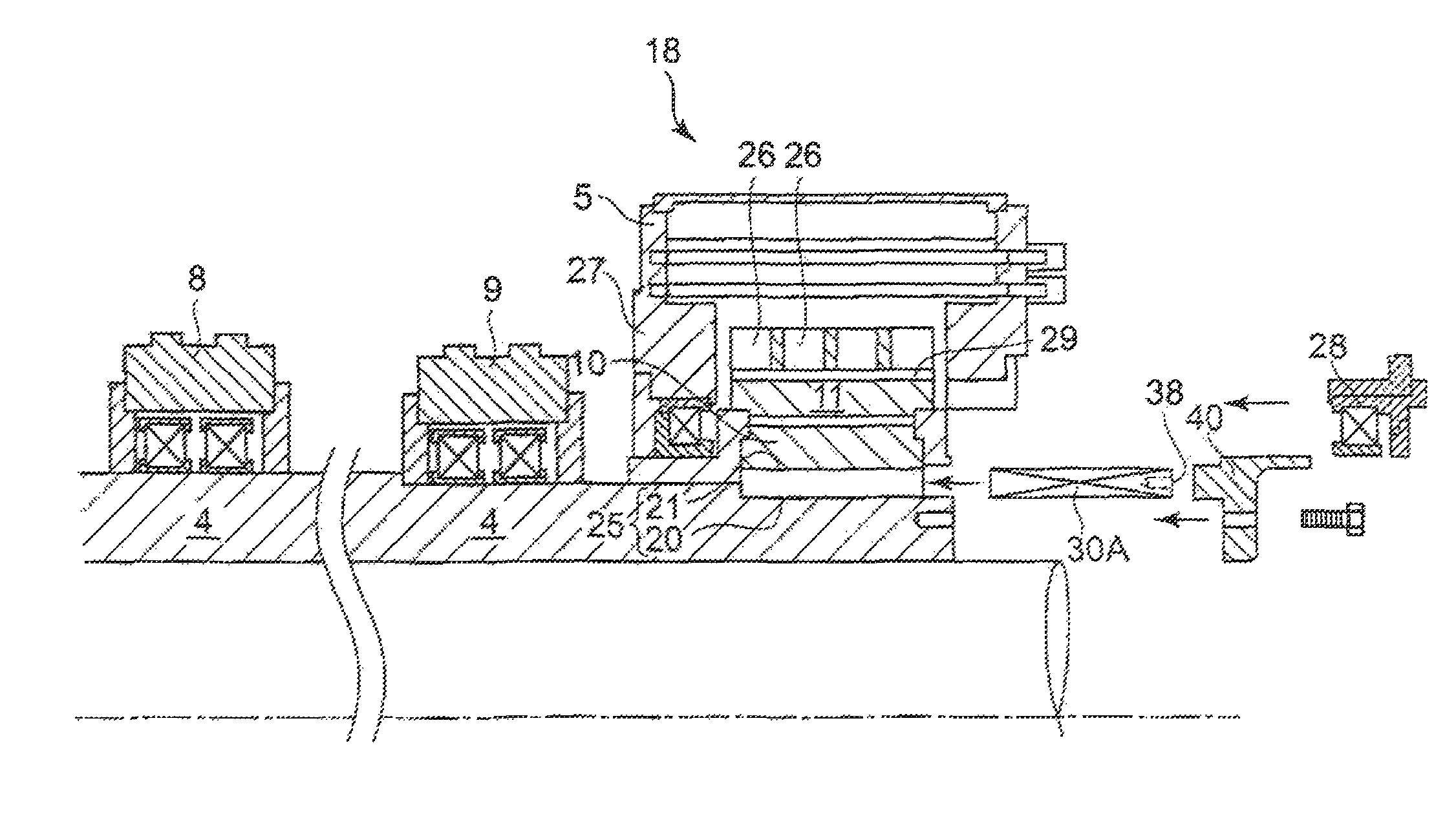
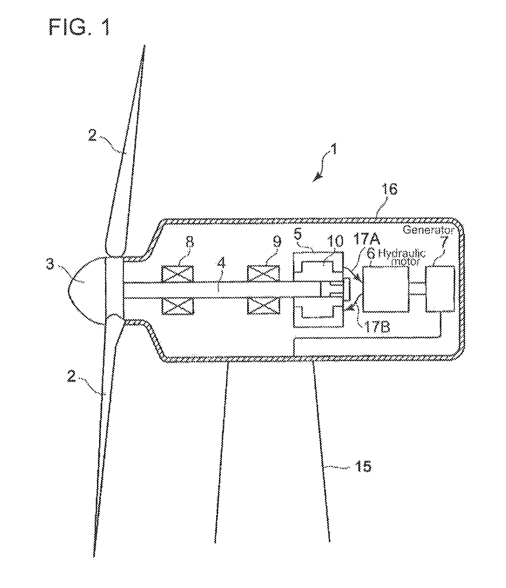
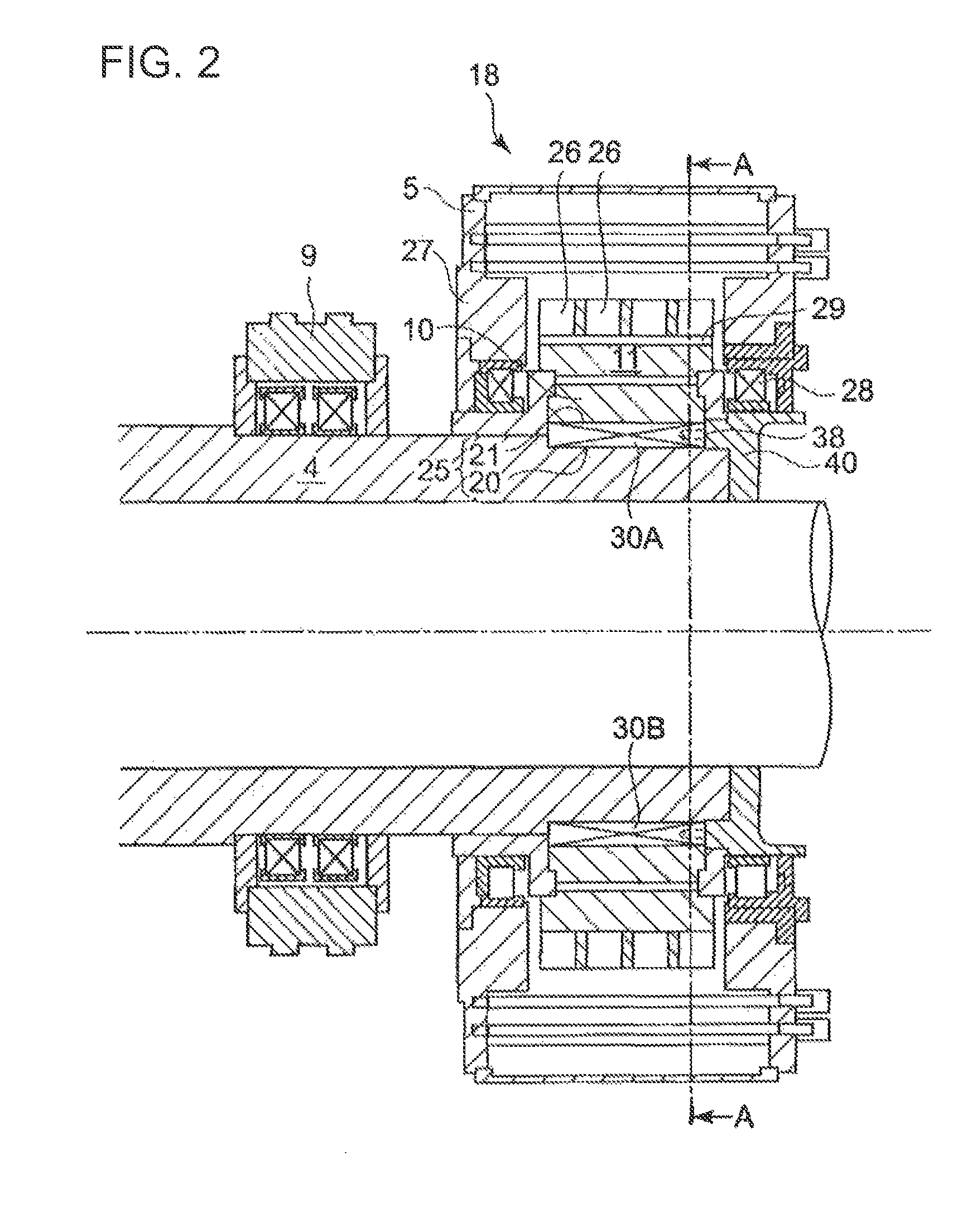
[0072]FIG. 1 is a schematic sectional view of a top part of a wind turbine generator in relation to a first preferred embodiment of the present invention. The wind turbine generator 1 in relation to the preferred embodiment includes a hub 3 to which blades 2 are installed, a main shaft 4 which is coupled to the hub 3 at one end, a hydrauli...


PUM

PropertyMeasurementUnit
pressureaaaaaaaaaa
rotation energyaaaaaaaaaa
rotation speedaaaaaaaaaa

Abstract

It is intended to provide a power generating apparatus of renewable energy type which can transmit large torque and has a low-cost and readily processable structure of fixing a hydraulic pump to the main shaft and a method of mounting the hydraulic pump. A plurality of key slots 25 are formed at an end on the back-end side of the main shaft 4. A plurality of keys 30A, 30B are inserted in the key slots 25. The keys 30A, 30B include a reference key 30A to be inserted in one of the key slots and a split key 30B to be inserted in the other of the key slots. The split key 30B is separated into a first key piece 34 having a projection to be inserted in a first groove formed in the main shaft and a second key piece 36 having a depression to be inserted in a second groove formed in the cylindrical member. The pair of key pieces 34, 36 are arranged so that the projection and the depression engage with each other. The projection and the depression of the first and second key pieces have side surfaces 34A, 34B, 36A and 36B formed along a radial direction of the main shaft 4. The side surfaces 34A, 34B, 36A and 36B are contact surfaces of the first and second key pieces 36 and incline with respect to the axial direction of the main shaft.

Description

RELATED APPLICATIONS[0001]The present application is continuation from PCT International Application of PCT / JP2011 / 058646 filed Apr. 5, 2011, the disclosure of which is hereby incorporated by reference herein in its entirety.TECHNICAL FIELD[0002]The present invention relates to a power generating apparatus of renewable-energy type which transmits rotation energy of a rotor to a generator via a hydraulic transmission which is a combination of a hydraulic pump and a hydraulic motor as well as a method for installing the hydraulic pump. The power generating apparatus of renewable-energy type uses renewable energy such, as wind, tidal current, ocean current and river current to generate power. There are, for instance, a wind turbine generating apparatus, a tidal current generating apparatus, an ocean current generating apparatus, a river current power generating apparatus and the like.BACKGROUND ART[0003]Recently, from the perspective of environmental protection, a wind turbine generato...

Claims


Application Information

Patent Timeline
Patent Type & Authority Patents(United States)
IPC IPC(8): F03D9/00
CPCF03D9/001F16D1/0882F05B2260/403Y10T29/49826Y02E10/721F03D9/28F03D9/25F03D80/70F03D15/00Y02E10/72Y02P80/10F04D9/00F03D1/06F16B3/00
Inventor TSUTSUMI, KAZUHISAICHIRYUU, TAKU
Owner MITSUBISHI HEAVY IND LTD
Why Eureka
Try Eureka