Connector device for joining multiple conductors

Active Publication Date: 2013-08-06
PATTEN JANEEN +1
View PDF15 Cites 13 Cited by
  • Summary
  • Abstract
  • Description
  • Claims
  • Application Information

AI Technical Summary

Benefits of technology

[0009]At least one compression nut having female threads matching the male threads of the tapered end is disposed around each tapered end. The compression nut

Problems solved by technology

The disadvantage of this type of connector is that there is only one point of contact for electrical conduction.
The crimp style of splice has the disadvantage of not providing a secure mechanical connection and/or a poor electrical connection

Method used


Image

  • Connector device for joining multiple conductors
  • Connector device for joining multiple conductors
  • Connector device for joining multiple conductors

Examples


Embodiment Construction

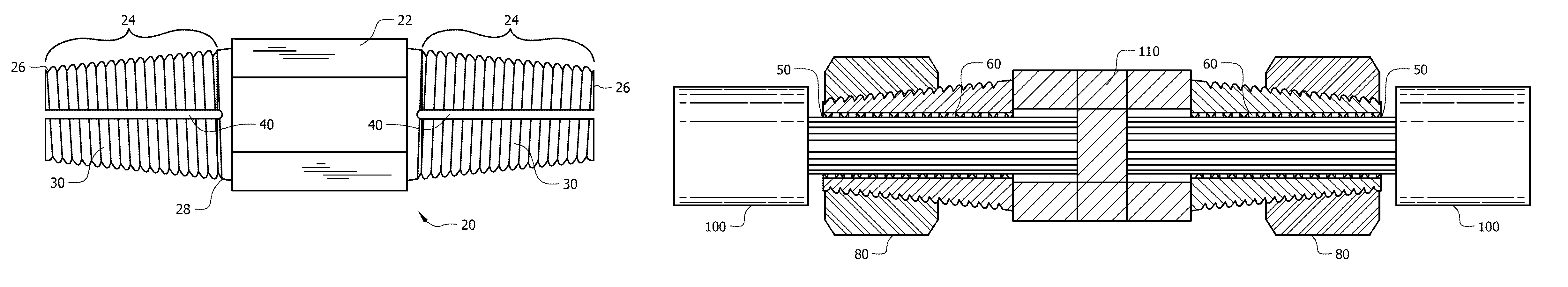
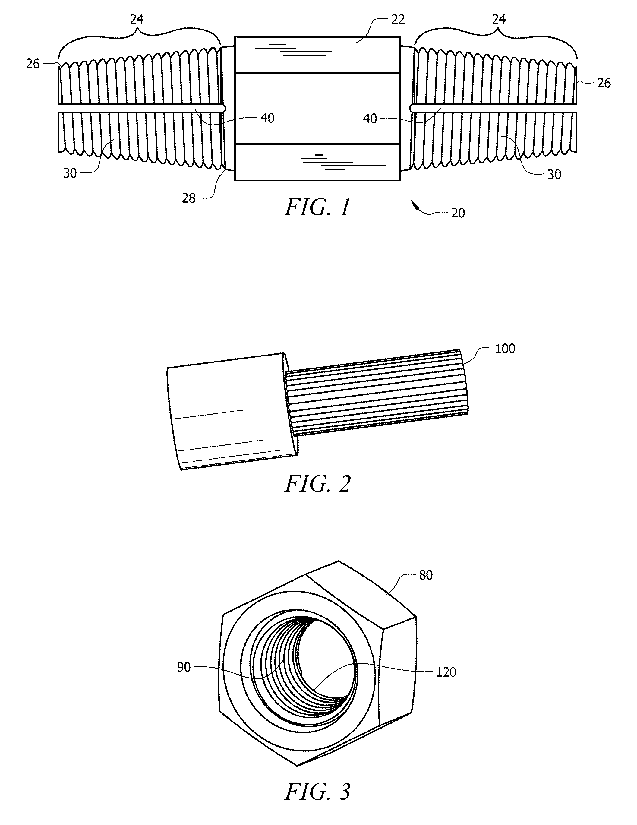
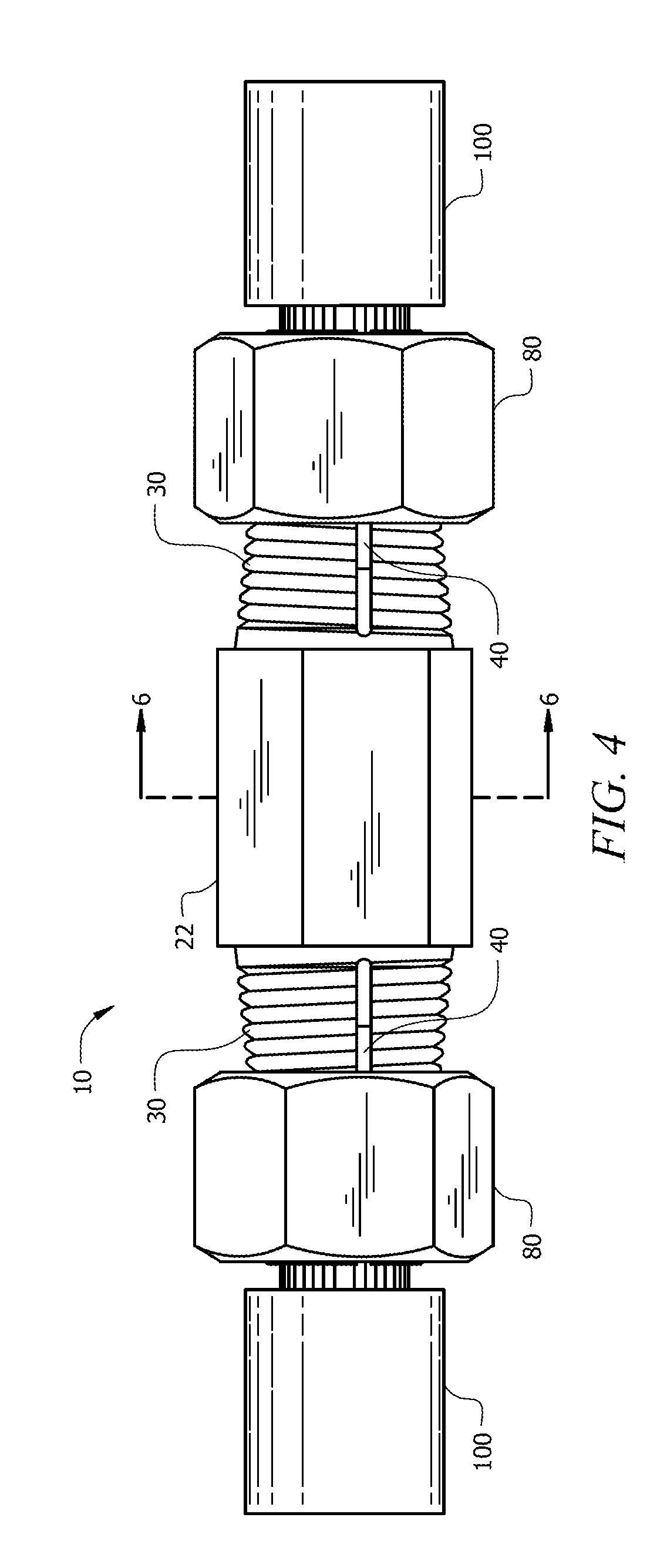
[0023]In the following detailed description of the preferred embodiments, reference is made to the accompanying drawings, which form a part hereof, and within which are shown by way of illustration specific embodiments by which the invention may be practiced. It is to be understood that other embodiments by which the invention may be practiced. It is to be understood that other embodiments may be utilized and structural changes may be made without departing from the scope of the invention.

[0024]The term “about” or “approximately” or “substantially” as used herein refers to being within an acceptable error range for the particular value as determined by one of ordinary skill in the art, which will depend in part on how the value is measured or determined, i.e. the limitations of the measurement system, including the degree of precision required for a particular purpose.

[0025]The term “conductor” as used herein refers to an electrical conductor of electricity. Examples of conductors i...


PUM


Abstract

A connector device and system for joining electrical conductors is presented. The connector device is comprised generally of an elongated body having at least two tapered ends. Each tapered end has male threads disposed on the exterior surface and at least one compression groove. A compression nut having an internal taper matching the angle of the taper of the tapered end is disposed on each tapered end. In use, a conductor is inserted into one tapered end and the compression nut is rotated towards the center of the elongated body thus compressing the compression grooves and providing enhanced mechanical stability and electrical conductivity by providing 360 degree contact of the connector device with the conductor.

Description

FIELD OF INVENTION[0001]This invention relates to connectors for joining conductors. Specifically, the invention provides a novel connector apparatus for joining at least 2 conductors which provides a 360 degree compression of each wire for improved mechanical and electrical connection.BACKGROUND OF THE INVENTION[0002]Electric cables generally consist of a conductive core (typically aluminum or copper) sometimes surrounded by insulating material. Electric cables generally can be divided into construction categories based on the type of voltage they are designed to carry. High voltages are generally those that are greater than about 50,000 volts; medium voltage are generally those that are between about 1000 volts and about 50,000 volts; and low voltage are those that are less than about 1000 volts.[0003]In order to electrically connect two or more conductors, it is necessary to form a splice or junction between the conductors. Electrical splice connectors for connecting at least two...

Claims


Application Information

Patent Timeline
IPC IPC(8): H01R11/09
CPCH01R4/5091H01R11/09
Inventor PATTEN, JOSEPH W.
Owner PATTEN JANEEN
Why Eureka
Try Eureka