
Image processing apparatus and method, recording medium, and program

a technology of image processing and recording media, applied in the field of image processing apparatus and methods, recording media, and programs, can solve the problems of inability to improve the excessive computational costs, and decrease in accuracy of detecting motion vectors, so as to improve image quality, reduce computational costs, and improve image quality

Inactive Publication Date: 2013-08-06
SONY CORP
View PDF25 Cites 3 Cited by
  • Summary
  • Abstract
  • Description
  • Claims
  • Application Information

AI Technical Summary

Benefits of technology

[0018]The present invention has been made in view of the situation described above, and it is an object of the present invention to accurately calculate motion vectors on a pixel-by-pixel basis, particularly in motion-compensating image processing based on motion vectors, and to obtain the degree of occurrence of error in pixels generated by interpolation to switch the method of generating pixels by interpolation, so that computational cost is reduced and so that image quality is improved by suppressing image distortion caused by block-based interpolation or mismatch between pixels generated by interpolation and peripheral pixels.
[0033]According to the present invention, computational cost is reduced, and image distortion that occurs due to block-based interpolation or mismatch between pixels generated by interpolation and peripheral pixels can be suppressed, serving to improve image quality.

Problems solved by technology

However, according to the method of detecting motion vectors by block matching, the accuracy of detecting motion vectors decreases when the block size is large, but the accuracy of detecting motion vectors does not improve even when the block size is chosen to be smaller than a certain value.
Furthermore, in block matching, the amount of computation becomes huge when the block size is small, resulting in excessive computational cost.

Method used


Image

  • Image processing apparatus and method, recording medium, and program
  • Image processing apparatus and method, recording medium, and program
  • Image processing apparatus and method, recording medium, and program

Examples


Embodiment Construction

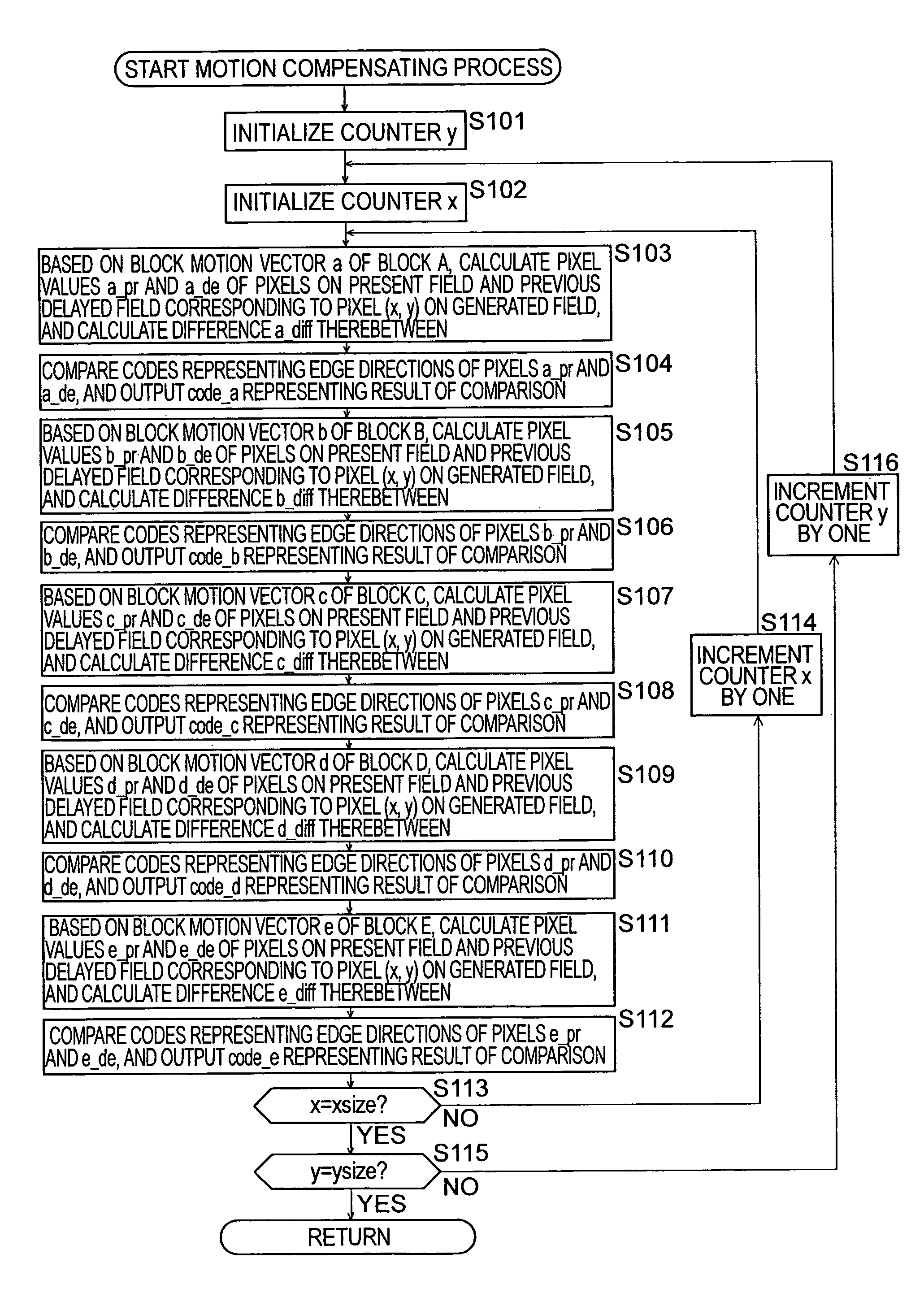
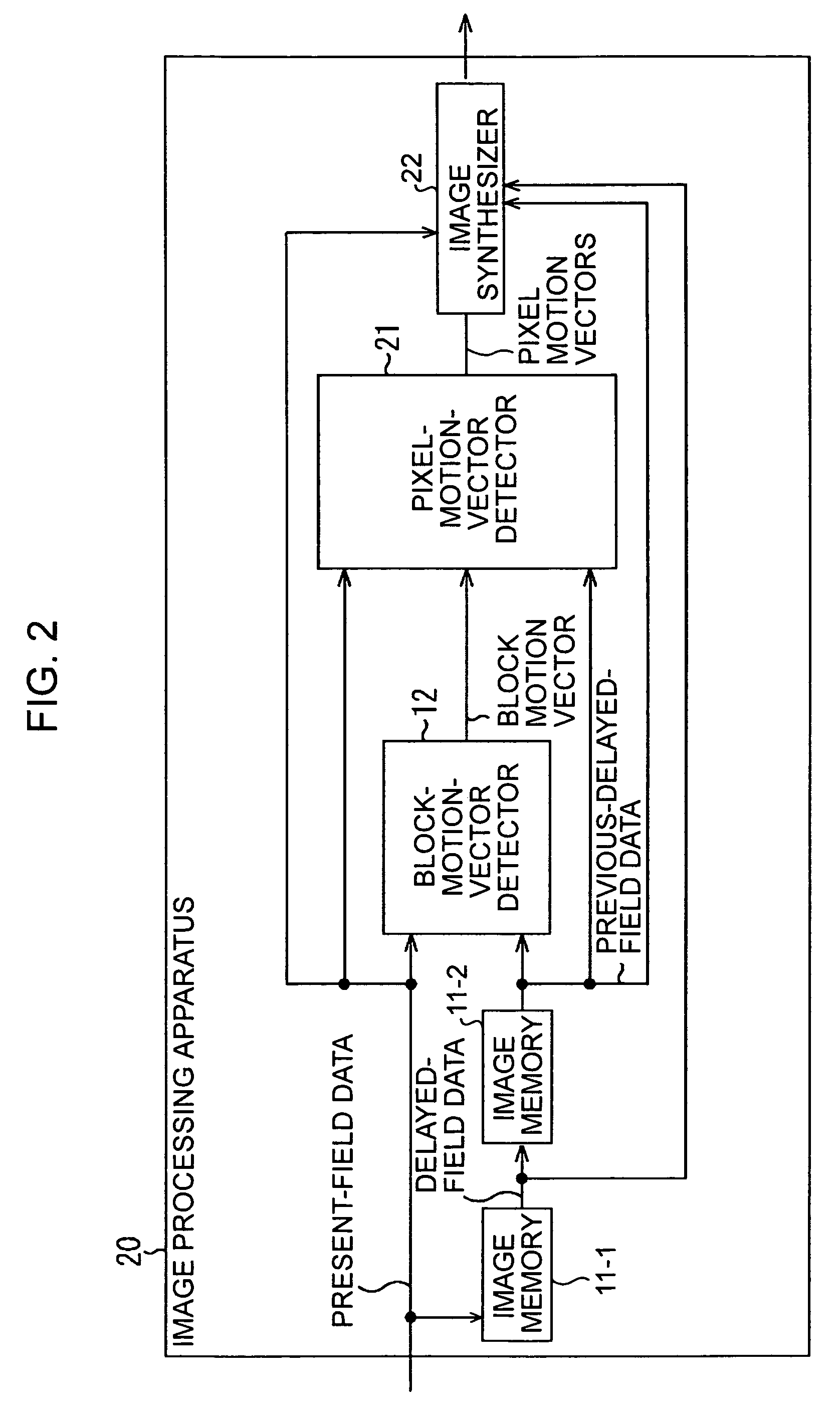
[0066]A first image processing apparatus according to the present invention includes a block-motion-vector detector (e.g., a block-motion-vector detector 12 shown in FIG. 2) for detecting, by block matching, respective block motion vectors of a block including a subject pixel and a plurality of blocks adjacent to the block including the subject pixel; a difference calculator (e.g., a motion compensator 36 shown in FIG. 3) for calculating difference between pixel values of a pixel on a first field and a pixel on a second field, these pixels being used to generate the subject pixel, based on each of the block motion vectors detected by the block-motion-vector detector; a pixel-motion-vector selector (e.g., a condition checker 37 shown in FIG. 3) for selecting, as a pixel motion vector of the subject pixel, one of the block motion vectors that minimizes the difference calculated by the difference calculator; and a pixel generator (e.g., an image synthesizer 22 shown in FIG. 2) for gene...


PUM


Abstract

With regard to a subject block including a subject pixel and four adjacent blocks vertically and horizontally adjacent to the subject block, respective motion vectors of these blocks are considered as candidates of a pixel motion vector of the subject pixel. The block motion vectors are actually applied to the subject pixel, and one of the motion vectors that minimizes difference between pixel values of pixels used for inter-field interpolation is selected as the pixel motion vector of the subject pixel.

Description

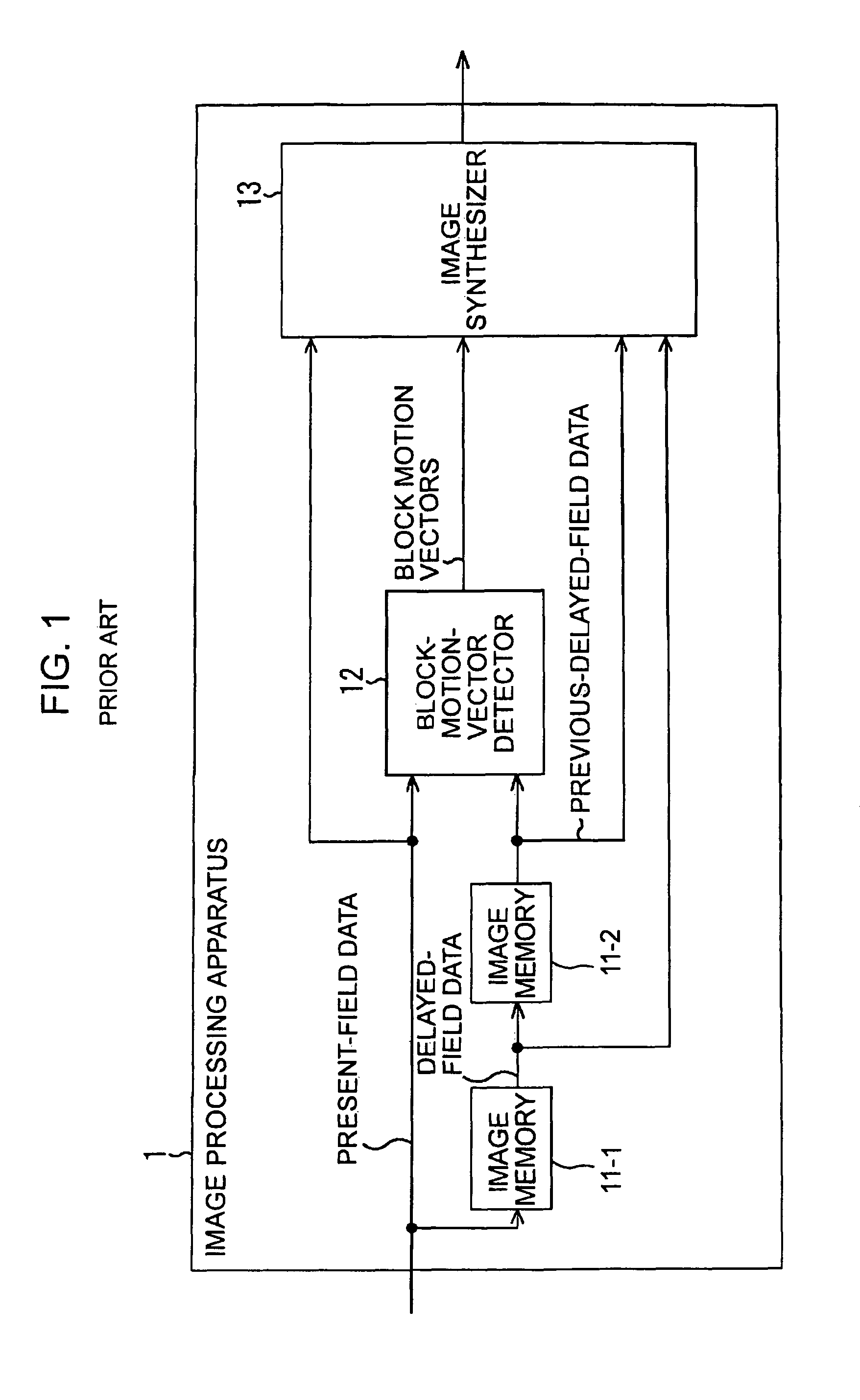
BACKGROUND OF THE INVENTION[0001]1. Field of the Invention[0002]The present invention relates to image processing apparatuses and methods, recording media, and programs. More specifically, the present invention relates to an image processing apparatus and method, a recording medium, and a program for accurately calculating motion vectors on a pixel-by-pixel basis and for switching the method of generating pixels in accordance with the amounts of error that occurs in pixels generated based on the motion vectors calculated.[0003]2. Description of the Related Art[0004]Techniques for generating new pixels based on pixels of an existing image to convert the resolution or field frequency of the image are becoming common.[0005]In one known method for generating pixels of a moving picture, motion vectors are used. A motion vector indicates a direction and a distance of movement of a pixel having temporally the same pixel value in a moving picture or the like.[0006]FIG. 1 shows the construct...

Claims


Application Information

Patent Timeline
Patent Type & Authority Patents(United States)
IPC IPC(8): H04N7/12G06T7/20G06T13/00G06T13/80
CPCG06T7/2013G06T7/2026G06T2207/10016G06T7/223G06T7/238B65B13/02B65B13/183B65B59/00
Inventor AOYAMA, KOJINISHIBORI, KAZUHIKOMICHEL, XAVIERKUROKAWA, MASUYOSHI
Owner SONY CORP
Learn More