
Beverage bottling plant having a filling machine with multiple beverage filling elements, a filling machine with multiple beverage filling elements, a filling element and related method

a beverage bottling plant and beverage technology, applied in the directions of liquid handling, packaging goods, transportation and packaging, etc., can solve the problems of significant contamination of the filling machine, gas shutoff valve located on the discharge opening of the filling element, and residual dripping from the filling elemen

Active Publication Date: 2013-08-13
KHS GMBH
View PDF19 Cites 11 Cited by
  • Summary
  • Abstract
  • Description
  • Claims
  • Application Information

AI Technical Summary

Benefits of technology

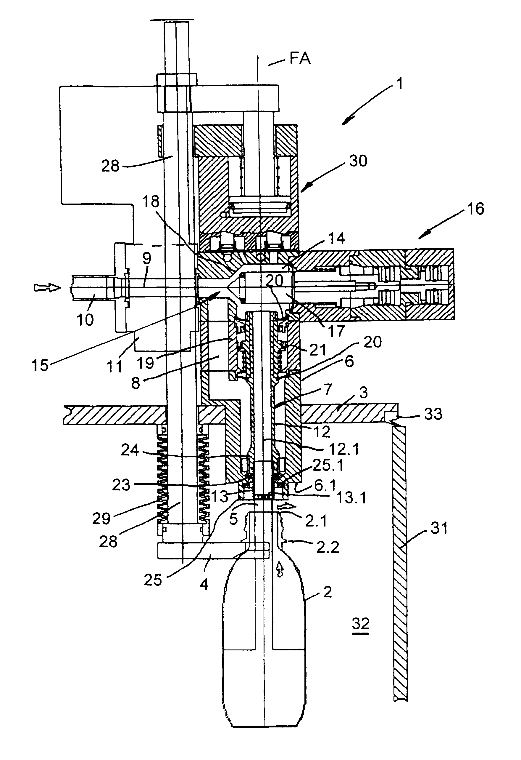
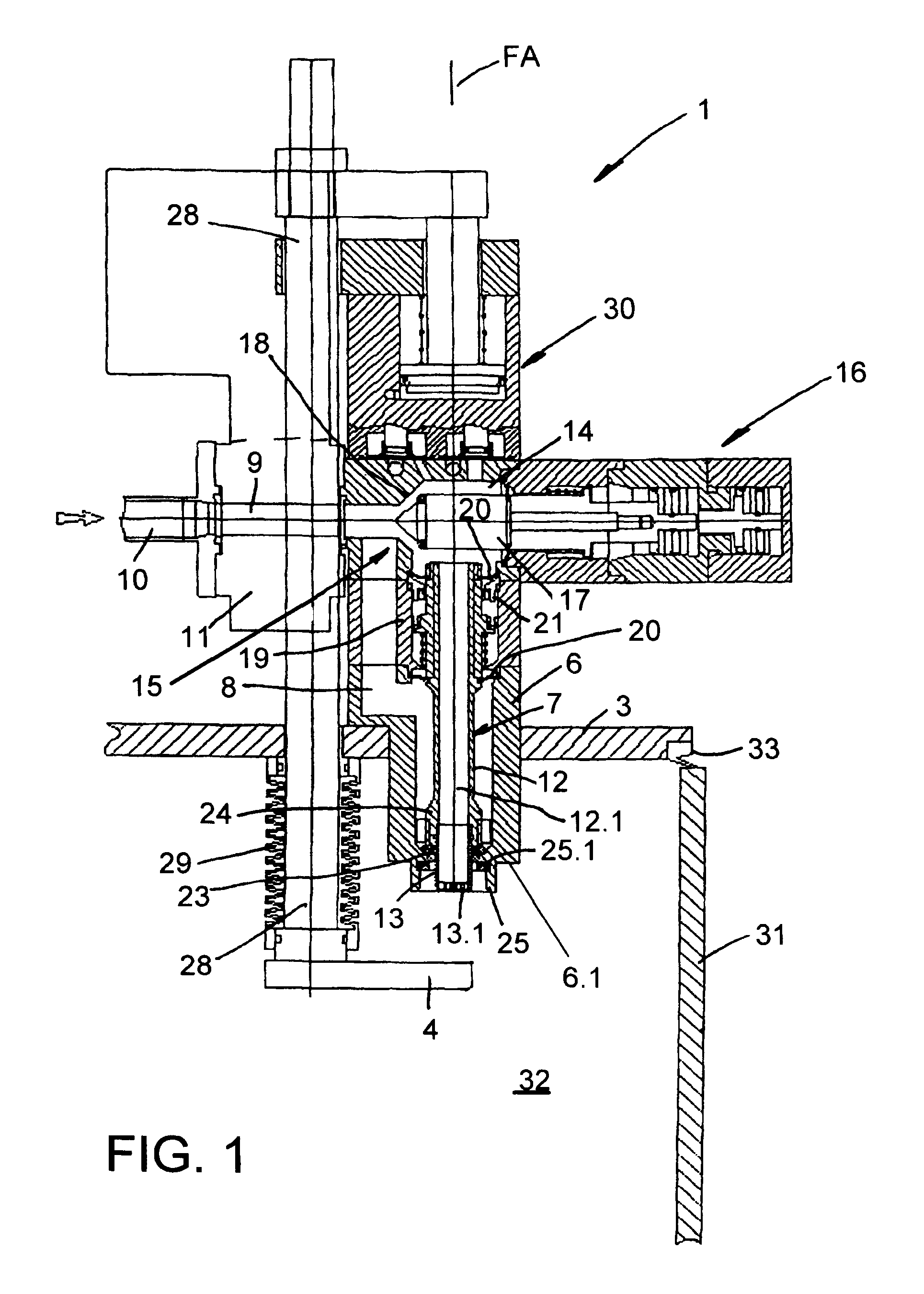
The present patent describes a filling element that allows for easy and problem-free switching between open-jet filling and pressure filling methods. The filling element includes a liquid duct with a controllable valve for delivering liquid to bottles or containers. Additionally, there is an additional flow duct with a gas shutoff valve for controlling the flow of liquid. The non-effervescent liquid beverage duct includes a valving arrangement and a gas shutoff element to minimize leakage of liquid. The changeover between the two filling methods can be carried out by controlling the corresponding valves without needing to install additional components on the filling element.

Problems solved by technology

One basic problem with open-jet filling is residual dripping from the filling element after the end of the filling phase and after the removal of the filled container from the container carrier.
However, a filling element with a gas shutoff valve located on its discharge opening cannot be used for pressure filling, possibly for the bottling of a carbonated liquid.
Consequently, the liquid is pushed through the gas shutoff valve, which possibly results in a significant contamination of the filling machine, which may be unacceptable, usually during cold aseptic bottling, on account of the high requirements for sterility.
If such filling elements are used both for open-jet filling and for pressure filling, to restrict or hinder dripping it is therefore desired, before the machine can be used for pressure filling, to remove the gas shutoff valves that are provided during the open-jet filling, and conversely to re-install the gas shutoff valves after pressure filling and before open-jet filling, which could potentially require a time-consuming and labor-intensive changeover of the respective filling machine and entails additional production costs as well as additional cleaning cycles.

Method used


Image

  • Beverage bottling plant having a filling machine with multiple beverage filling elements, a filling machine with multiple beverage filling elements, a filling element and related method
  • Beverage bottling plant having a filling machine with multiple beverage filling elements, a filling machine with multiple beverage filling elements, a filling element and related method
  • Beverage bottling plant having a filling machine with multiple beverage filling elements, a filling machine with multiple beverage filling elements, a filling element and related method

Examples


Embodiment Construction

[0030]As used herein, the term “open-fill” includes filling beverage containers, i.e. bottles, cans and the like, with a liquid beverage that does not have to be stored under pressure for filling. Hence, the connection between filling element of a typical filling machine and the container into which liquid beverage will be deposited can be kept open to the air and surrounding environs. It does not have to be maintained under set pressure conditions. By contrast, the term “pressurized” or “pressure-fill” means a beverage bottling filling arrangement for receiving a liquid beverage material stored under pressure by a gas. This arrangement is especially suited for the bottling of effervescent, or “carbonated” beverages, including sodas and the like.

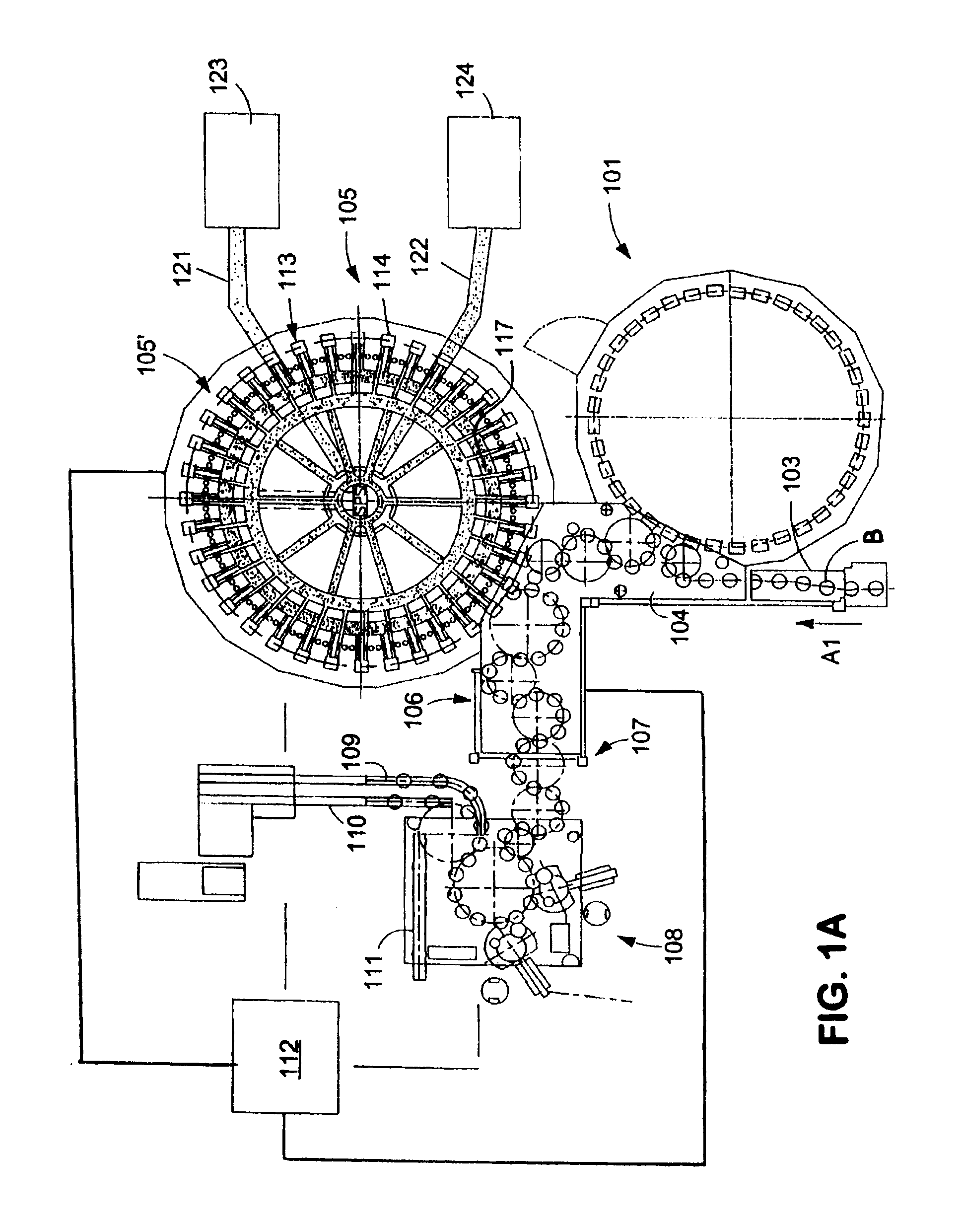
[0031]FIG. 1A shows schematically the main components of one possible embodiment example of a system for filling containers, specifically, a beverage bottling plant for filling bottles B with at least one liquid beverage, in accordance with ...


PUM


Abstract

A container filling element for filling containers with a liquid. The filling element has two liquid ducts and two separate discharge openings in a housing, as well as separate valves which control the flow of liquid for each liquid duct and discharge opening. A gas shutoff element is disposed in one of the liquid ducts and is positioned adjacent to each of the discharge openings.

Description

CONTINUING APPLICATION DATA[0001]This application is a continuation application of co-pending U.S. application Ser. No. 12 / 250,855, filed Oct. 14, 2008. U.S. application Ser. No. 12 / 250,855 is a Continuation-In-Part application of International Patent Application No. PCT / EP2007 / 002998, filed on Apr. 3, 2007, which claimed priority from Federal Republic of Germany Patent Application No. 10 2006 017 706.1, filed on Apr. 15, 2006. The United States was an elected state in International Patent Application No. PCT / EP2007 / 002998.BACKGROUND[0002]1. Technical Field[0003]This present application relates to a beverage bottling plant, a filling element, a filling machine and related methods.[0004]2. Background Information[0005]Background information is for informational purposes only and does not necessarily admit that subsequently mentioned information and publications are prior art.[0006]There are various models of filling elements for use in filling machines, possibly in filling machines th...

Claims


Application Information

Patent Timeline
Patent Type & Authority Patents(United States)
IPC IPC(8): B65B3/04
CPCB67C3/004B67C3/20B67C3/242B67C3/244B67C3/2608B67C3/2617B67C3/023
Inventor KRULITSCH, DIETER-RUDOLF
Owner KHS GMBH
Learn More