Camera with color correction after luminance and chrominance separation

a technology of luminance and chrominance separation and color correction, applied in the field of digital cameras, can solve the problems of color correction increasing noise in some colors, difficult or even expensive determination or even approximation of noise standard deviation after color correction, and reducing luminance and chrominance noise. , to achieve the effect of minimizing color-dependent noise, providing luminance and chrominance noise reduction, and different noise filtering for luminan

Active Publication Date: 2013-08-13
AMBARELLA INT LP
View PDF6 Cites 11 Cited by
  • Summary
  • Abstract
  • Description
  • Claims
  • Application Information

AI Technical Summary

Benefits of technology

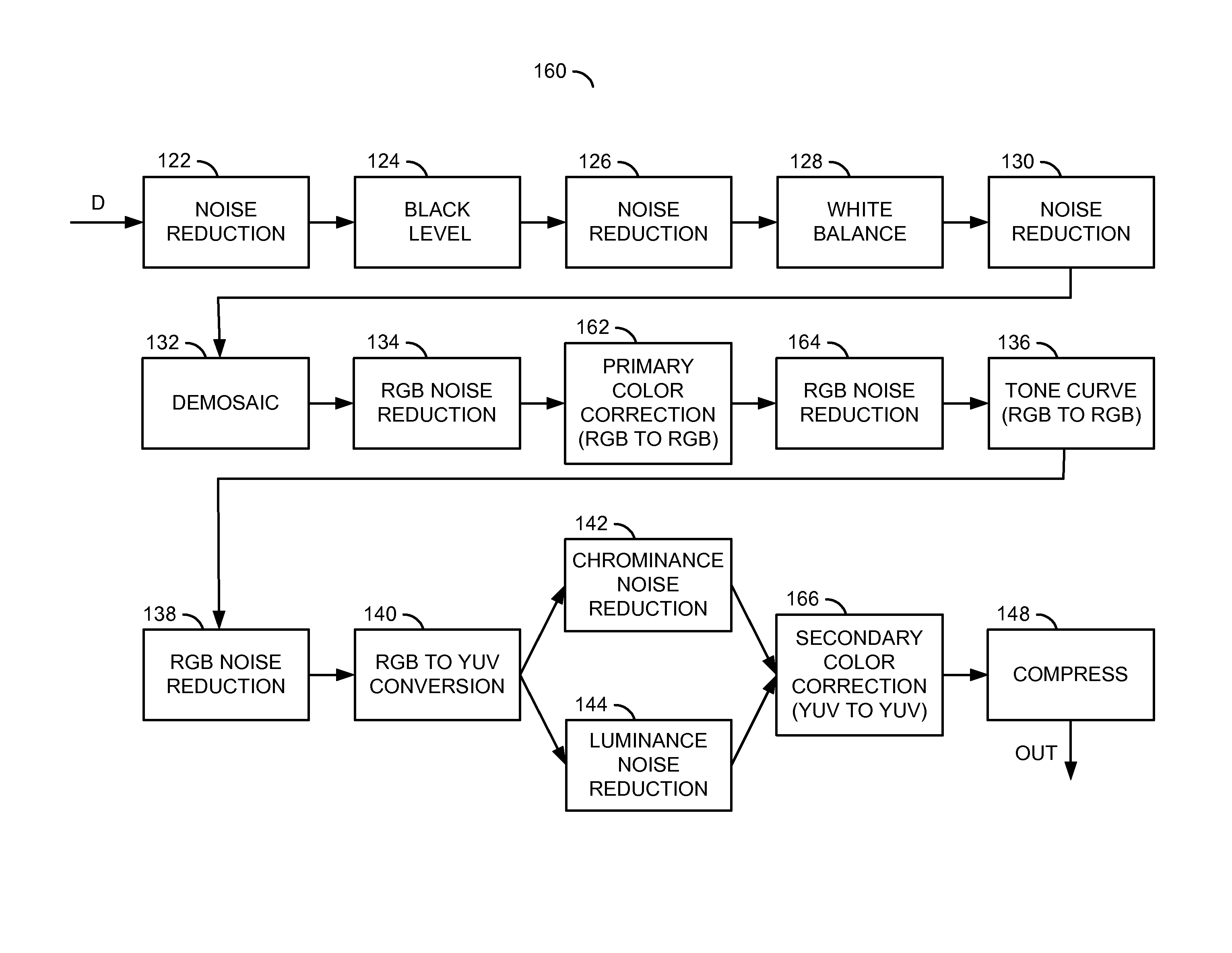
[0013]The objects, features and advantages of the present invention include providing a camera with color correction after luminance and chrominance separation that may (i) perform color correction after a conversion to a YUV color space, (ii) provide luminance and chrominance noise reduction prior to the color correction, (iii) minimize color-dependent noise, and / or (iv) provide different noise filtering for luminance than for chrominance.

Problems solved by technology

Color correction is commonly used in digital cameras because a spectral response of the camera photo-receptors does not match a desired response in an output color space.
Unfortunately, the amplitude of noise, especially in some colors, can be greatly increased by the color correction.
As described earlier, color correction can increase noise in some colors.
Due to the color-dependent noise amplification, a determination or even approximation of the noise standard deviation after color correction can be difficult or expensive, especially if the color correction process is complex.
However, the effectiveness of such noise reductions can be degraded by occurring after the color correction.

Method used


Image

  • Camera with color correction after luminance and chrominance separation
  • Camera with color correction after luminance and chrominance separation
  • Camera with color correction after luminance and chrominance separation

Examples


Embodiment Construction

[0022]Referring to FIG. 4, a block diagram of an example implementation of an apparatus 100 is shown. The apparatus (or system) 100 may form a digital still camera and / or camcorder. The apparatus 100 generally comprises a circuit (or module) 102, a circuit (or module) 104, a circuit (or module) 106, a circuit (or port) 107, a circuit (or module) 108 and a circuit (or module) 110. An optical signal (e.g., LIGHT) may be received by the circuit 102. The circuit 102 may generate and present a digital signal (e.g., D) to the circuit 104. A synchronization signal (e.g., SYNC) may also be generated by the circuit 102 and received by the circuit 104. A sensor control signal (e.g., SCNT) may be generated and presented from the circuit 104 to the circuit 102. A signal (e.g., OUT) may be exchanged between the circuit 104 and the circuit 108. The circuit 104 may generate and present a signal (e.g., VIDEO) through the interface 107 to a monitor outside the apparatus 100. A command signal (e.g., ...


PUM


Abstract

An apparatus having a circuit is disclosed. The circuit may be configured to (i) receive a digital image from an electro-optical sensor, (ii) convert the digital image from a red-green-blue representation to a luminance-and-chrominance representation, (iii) generate a reduced noise representation of the digital image by reducing noise in the luminance-and-chrominance representation and (iv) generate a color corrected representation of the digital image by color correcting the reduced noise representation.

Description

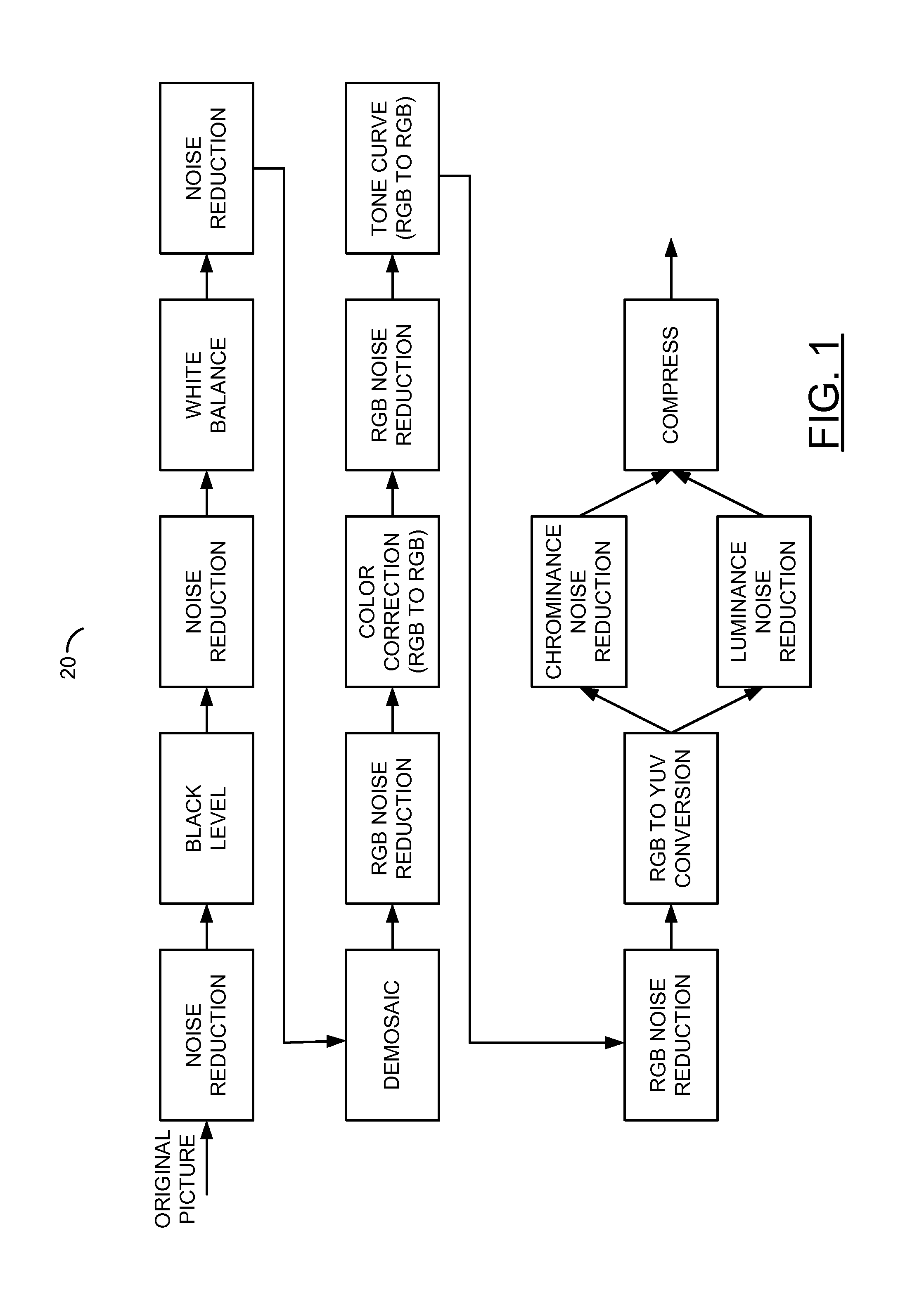
CROSS REFERENCE TO RELATED APPLICATIONS[0001]The present application is related to co-pending U.S. application Ser. No. 12 / 706,816 filed Feb. 17, 2010, and Ser. No. 12 / 712,307 filed Feb. 25, 2010, and U.S. Pat. No. 7,536,487, which are hereby incorporated by reference in their entirety.FIELD OF THE INVENTION[0002]The present invention relates to a method and / or architecture for digital cameras generally and, more particularly, to a camera with color correction after luminance and chrominance separation.BACKGROUND OF THE INVENTION[0003]A conventional camera sensor employs filters that pass through red, green, and blue light to different pixels on a sensor. The color measured on the sensor (Bayer values) is not the final color representation used in the picture, as a conventional camera will have the following steps: (i) black level subtraction, (ii) white balance, (iii) demosaic (generating RGB triples for each pixel from the sensor Bayer Color Filter Array (CFA) pattern), (iv) color...

Claims


Application Information

Patent Timeline
Patent Type & Authority Patents(United States)
IPC IPC(8): H04N9/68
CPCH04N9/646
Inventor LINZER, ELLIOT N.
Owner AMBARELLA INT LP
Why Eureka
Try Eureka