Control apparatus for hybrid vehicle

a hybrid vehicle and control apparatus technology, applied in the direction of electric devices, process and machine control, instruments, etc., can solve the problems of difficult to accurately detect and inability to detect the presence of this type of drag torque, so as to reduce the system efficiency of the hybrid vehicle, accurately detect the drag torque, and reduce the effect of system efficiency

Active Publication Date: 2013-08-13
TOYOTA JIDOSHA KK
View PDF24 Cites 1 Cited by
  • Summary
  • Abstract
  • Description
  • Claims
  • Application Information

AI Technical Summary

Benefits of technology

[0018]On the other hand, the locking mechanism of the present invention can adopt a state in which the first rotational element is not completely released from the fixed element (hereinafter, referred to as an “intermediate state” as occasion demands), as the intermediate state between the lock state and the non-lock state in terms of its structure. In the intermediate state, the first rotational element receives the drag torque as a type of braking torque to a varying degree from the fixed element fixed in the lock state, and the rotation of the first rotational element is interrupted to some extent. The drag torque is namely a loss torque which can reduce a torque transmitted to the drive shaft, and it is a factor which reduces the system efficiency of the hybrid drive apparatus. The presence of the drag torque as described above is extremely undesirable in view of the role of the locking mechanism which can be installed originally for the purpose of the high efficiency of the hybrid drive apparatus.
[0061]As described above, by selecting the speed change mode with the system efficiency as a judgment index, it is possible to reduce an influence of a loss by the drag torque as much as possible and to make the hybrid vehicle perform the retreat running, efficiently.

Problems solved by technology

The generation of the drag torque of this type is similar to a type of failure in the locking mechanism; however, in a conventional technology including the disclosures in the aforementioned patent documents, the presence of the drag torque is not considered, and inevitably, a technical idea associated with the detection of the drag torque is neither disclosed nor implied.
Therefore, it must be said that it is impossible to detect the presence of this type of drag torque simply from the rotational speed of the rotating electrical machine.
In other words, the conventional technology has such a technical problem that even if the drag torque is generated, it is practically hard to accurately detect it.

Method used


Image

  • Control apparatus for hybrid vehicle
  • Control apparatus for hybrid vehicle
  • Control apparatus for hybrid vehicle

Examples


first embodiment

Configuration of Embodiment

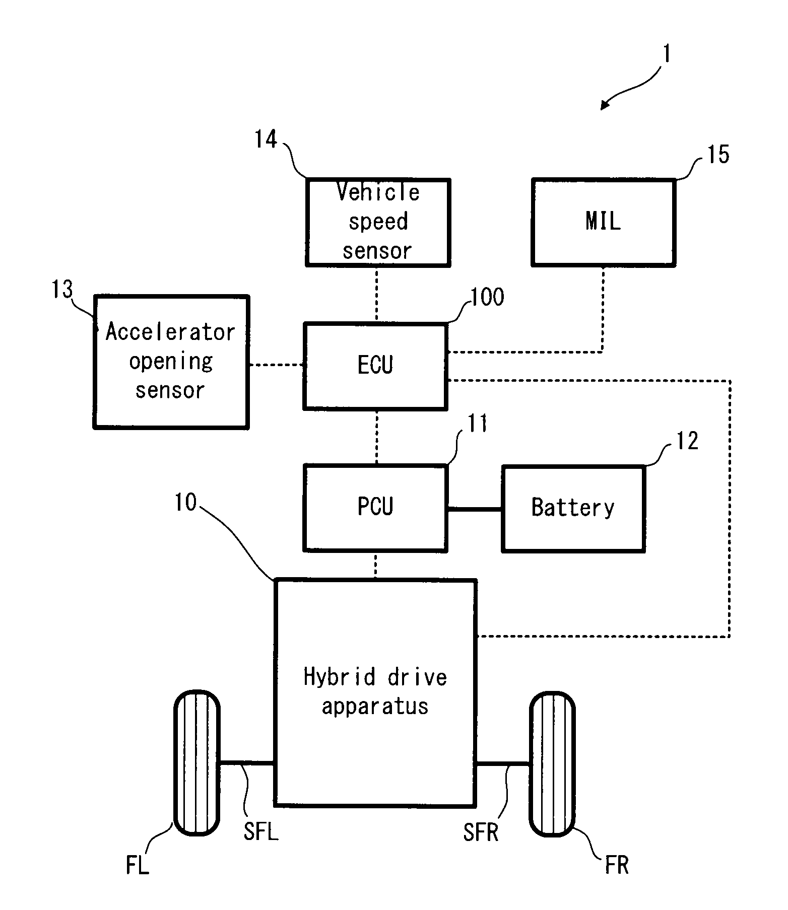
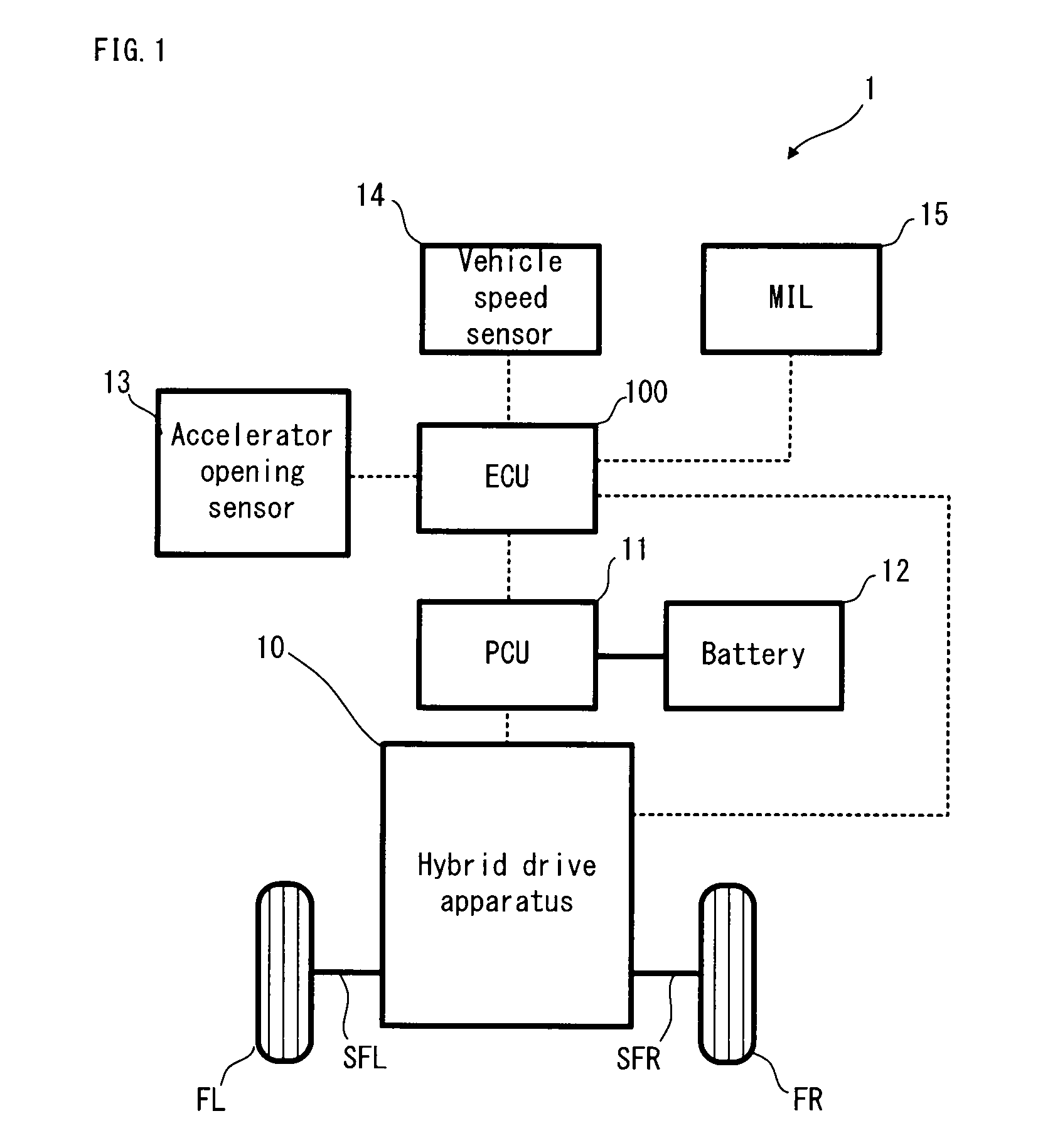
[0085]Firstly, with reference to FIG. 1, an explanation will be given on the structure of a hybrid vehicle 1 in a first embodiment of the present invention. FIG. 1 is a schematic configuration diagram conceptually showing the structure of the hybrid vehicle 1.

[0086]In FIG. 1, the hybrid vehicle 1 is provided with: an ECU 100; a Power Control Unit (PCU) 11; a battery 12; an accelerator opening sensor 13; a vehicle speed sensor 14; and a hybrid drive apparatus 10. The hybrid vehicle 1 is one example of the “hybrid vehicle” of the present invention.

[0087]The ECU 100 is provided with a Central Processing Unit (CPU), a Read Only Memory (ROM), a RAM and the like. The ECU 100 is an electronic control unit capable of controlling the operations of each part of the hybrid vehicle 1. The ECU 100 is one example of the “control apparatus for the hybrid vehicle” of the present invention. The ECU 100 can perform drag torque detection control described later, in accordanc...

second embodiment

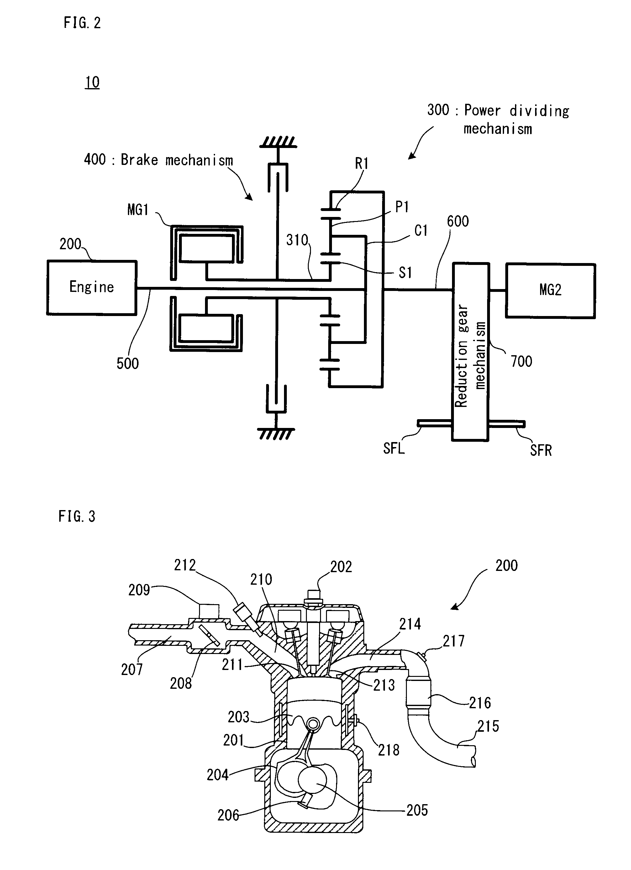
[0159]In the aforementioned first embodiment, the MG1 is locked when the hybrid drive apparatus 10 adopts the fixed speed change mode. However, the configuration of the hybrid drive apparatus in obtaining the fixed speed change mode is not limited to this type of MG1 locking. Now, with reference to FIG. 10, the configuration of another hybrid drive apparatus will be explained. FIG. 10 is a schematic configuration diagram conceptually showing the structure of a hybrid drive apparatus 20. Incidentally, in FIG. 10, portions overlapping those of FIG. 2 will carry the same reference numerals, and the explanation thereof will be omitted as occasion demands.

[0160]In FIG. 10, the hybrid drive apparatus 20 has a different structure from that of the hybrid drive apparatus 10 in that it is provided with a power dividing mechanism 800 as another example of the “power transmission mechanism” of the present invention, instead of the power dividing mechanism 300. The power dividing mechanism 800 a...

third embodiment

[0165]Next, a third embodiment of the present invention will be explained.

Configuration of Embodiment

[0166]Firstly, with reference to FIG. 11, an explanation will be given on the structure of a hybrid drive apparatus 30 in the third embodiment of the present invention. FIG. 11 is a schematic configuration diagram conceptually showing the structure of the hybrid drive apparatus 30. Incidentally, in FIG. 11, portions overlapping those of FIG. 2 will carry the same reference numerals, and the explanation thereof will be omitted as occasion demands.

[0167]Incidentally, the configuration of the vehicle in the third embodiment is the same as that of the hybrid vehicle 1, except that it is provided with the hybrid drive apparatus 30. Moreover, in the third embodiment, the ECU 100 can perform speed change control described later in accordance with a control program stored in the ROM. The ECU 100 is configured to function as one example of each of the “third controlling device”, the “calculat...


PUM


Abstract

An object of the present invention is to detect the generation of a drag torque in a locking mechanism, in a hybrid vehicle in which a speed change mode can be changed between a fixed speed change mode and a stepless speed change mode by the action of the locking mechanism. In a hybrid vehicle, a brake mechanism is a wet multiplate brake apparatus and can selectively lock a motor generator. On the other hand, in a case where the drag torque is generated in the brake mechanism, if the motor generator is in a positive rotation state, an actual motor generator torque (first torque) is greater than a torque (less as a reaction torque, second torque) calculated from the operating condition of the hybrid vehicle by the amount of the drag torque. If the motor generator is in a negative rotation state, the first torque is less (greater as the reaction torque) than the second torque. The ECU uses this phenomenon to detect the drag torque.

Description

TECHNICAL FIELD[0001]The present invention relates to an apparatus for controlling a hybrid vehicle provided with a locking mechanism for changing a speed change mode.BACKGROUND ART[0002]As this type of hybrid vehicle, there is one that can lock a generator (e.g. refer to a patent document 1). According to the hybrid vehicle disclosed in the patent document 1, it can reduce a shock in the locking by reducing the number of revolutions of a locking mechanism close to zero and then performing engagement.[0003]Incidentally, there has been also suggested a hybrid vehicle having a fixed transmission gear ratio mode and a stepless transmission gear ratio mode (e.g. refer to a patent document 2).PRIOR ART DOCUMENTPatent Document[0004]Patent document 1: Japanese Patent Application Laid Open No. Hei 9-156387[0005]Patent document 2: Japanese Patent Application Laid Open No. 2004-345527DISCLOSURE OF INVENTIONSubject to be Solved by the Invention[0006]As the locking mechanism, various engagement...

Claims


Application Information

Patent Timeline
Patent Type & Authority Patents(United States)
IPC IPC(8): B60W20/00B60L50/16B60W10/115B60W30/18
CPCB60K6/445B60K6/547B60L11/123B60L11/14B60L15/20B60W10/06B60W10/08B60W10/115B60W20/00B60W30/18072B60K6/365B60K1/02Y02T10/7275B60L2210/40B60L2220/14B60L2240/12B60L2240/423B60L2240/441B60L2240/443B60L2240/445B60L2270/145B60W2710/083Y02T10/6217Y02T10/6239Y02T10/642Y02T10/7077Y02T10/7241Y02T10/6286B60L50/16B60L50/61Y02T10/62Y02T10/64Y02T10/70Y02T10/7072Y02T10/72B60W10/026B60W10/11B60W10/18B60W20/30
Inventor KANNO, YOSHIHITOEBUCHI, HIROAKIKITABATAKE, HIROTATSUKIMURA, HIROMICHIIDESHIO, YUKIHIKOONO, TOMOHITOSANO, HIDEKI
Owner TOYOTA JIDOSHA KK
Why Eureka
Try Eureka