Determining an accumulated load of a wind turbine in angular sectors

a technology of accumulating load and wind turbine, which is applied in the direction of machines/engines, instruments, force/torque/work measurement apparatus, etc., can solve the problems of wind turbine, wind turbine, wind turbine foundation and/or tower structure damage, etc., and achieve accurate and reliable results.

Inactive Publication Date: 2013-08-20
SIEMENS GAMESA RENEWABLE ENERGY AS
View PDF11 Cites 15 Cited by
  • Summary
  • Abstract
  • Description
  • Claims
  • Application Information

AI Technical Summary

Benefits of technology

[0016]According to this embodiment, it is taken into account along which direction the load is acting and the experienced load is monitored in an angularly resolved manner such as to associate each angular sector with a respective experienced mechanical load. By determining the mechanical load for a number of different angular sectors the actually experienced load in each sector can be monitored more accurately, enabling a very accurate estimation of the load experienced in the different sectors.
[0042]According to an embodiment, a method of controlling a wind turbine is provided, wherein the method comprises performing a method of determining a total mechanical load of a wind turbine, as described above, and controlling the wind turbine based on the determined total mechanical load. For example, the wind turbine may be shut down or the operation of the wind turbine may be altered in dependence of the determined total mechanical load. Thereby, a safe operation of the wind turbine may be ensured. In particular, the wind turbine may be operated for longer times than when the wind turbine would be operated based on load estimation of a conventional method.

Problems solved by technology

Due to impact of wind on a wind turbine, components of the wind turbine, in particular components below a nacelle of the turbine which have a fixed position relative to a ground may experience strain, stress and wear.
In particular, the tower structure and / or the foundation of the wind turbine may be impaired over time due to the load experienced by the impacting wind.
However, it has been observed that conventional methods for determining a load of a wind turbine are not satisfactory in terms of accuracy such that the actual load of the wind turbine may deviate from the load estimated by the respective prediction method.

Method used


Image

  • Determining an accumulated load of a wind turbine in angular sectors
  • Determining an accumulated load of a wind turbine in angular sectors
  • Determining an accumulated load of a wind turbine in angular sectors

Examples


Embodiment Construction

[0052]The illustration in the drawings is in schematic form. It is noted that in different figures, similar or identical elements are provided with the same reference signs or with reference signs, which are different from the corresponding reference signs only within the first digit.

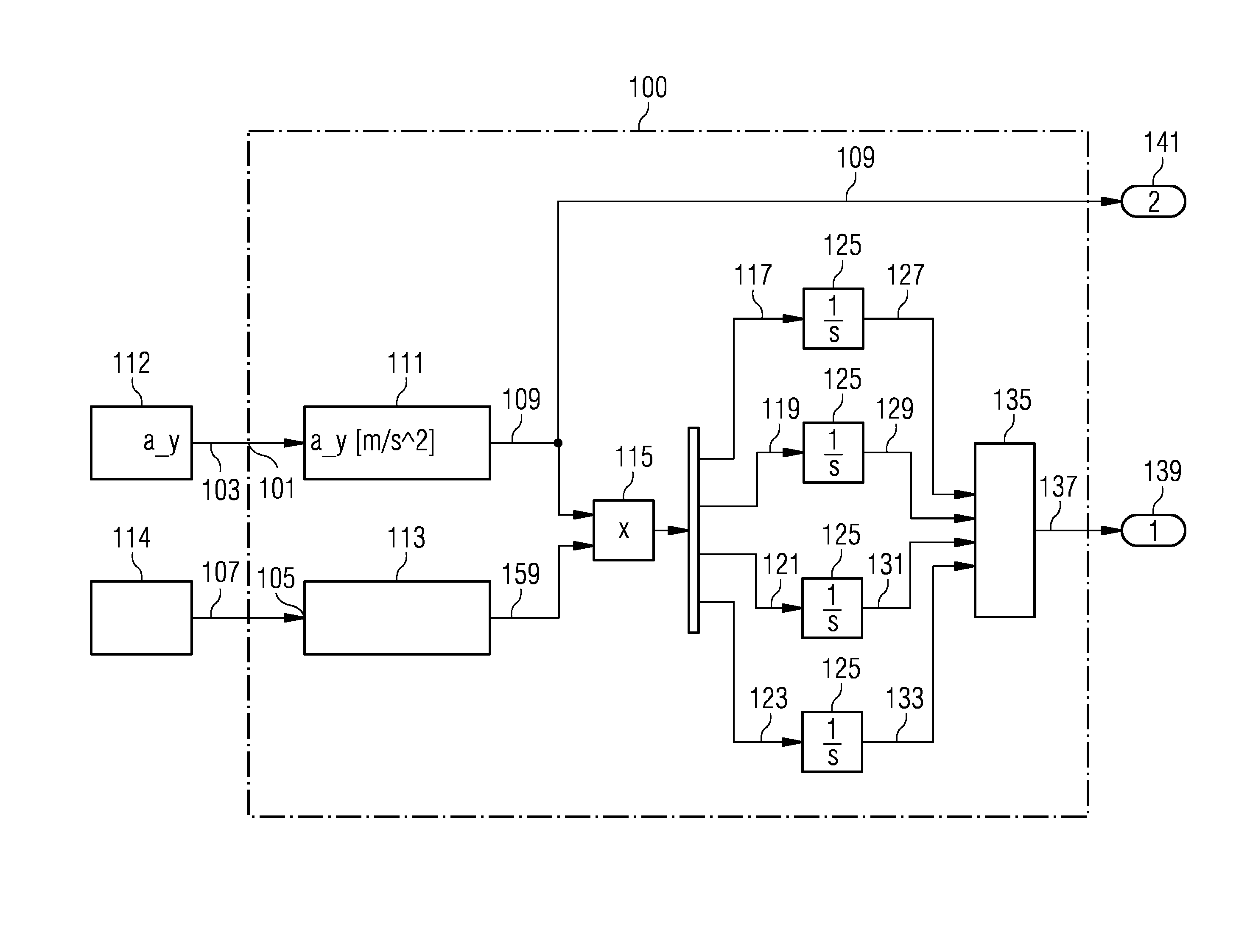
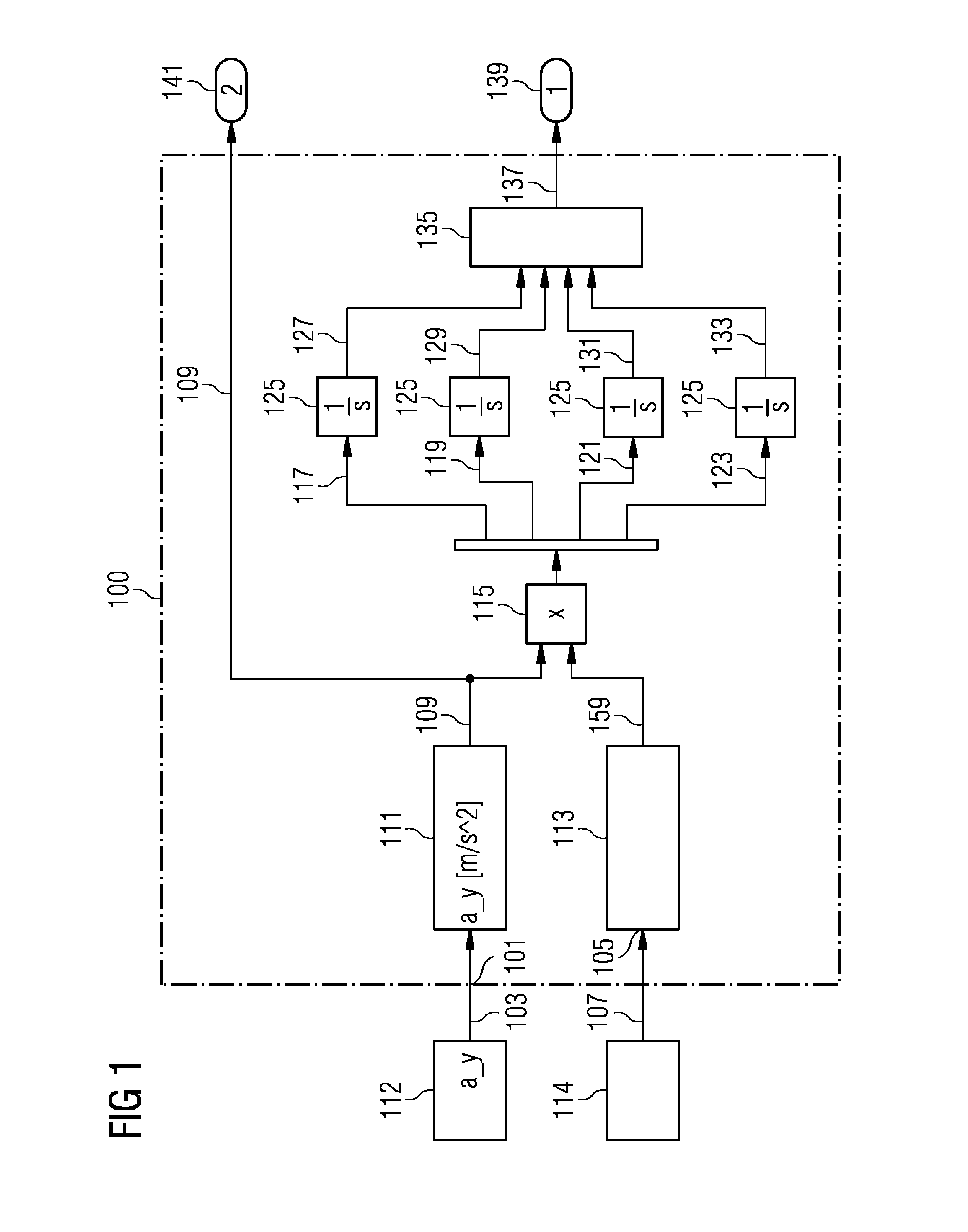
[0053]FIG. 1 schematically illustrates an arrangement 100 for determining a total mechanical load of a not illustrated wind turbine according to an embodiment.

[0054]The arrangement 100 comprises an input terminal 101 for receiving an acceleration signal 103 provided by an accelerometer 112, and an input terminal 105 for receiving a signal 107 indicative of a yaw position of the nacelle of the wind turbine provided by a yaw sensor 114. In this embodiment a present load signal 109 is derived from a load estimator 111 which is provided with the acceleration signal 103. In particular, the acceleration signal a_y corresponds to an acceleration in the forward-afterward-direction of the wind turbine representi...


PUM

PropertyMeasurementUnit
angleaaaaaaaaaa
angleaaaaaaaaaa
angleaaaaaaaaaa

Abstract

A method for determining a total mechanical load of a wind turbine is provided. A present load signal indicative of a present load of a wind turbine base structure is obtained, wherein the present load acts in a present angular direction. A first present load and a second present load are derived based upon the present load signal and the present angular direction, wherein the first present load is associated with a first angular sector of the turbine and the second present load is associated with a second angular sector of the turbine. Further, a total mechanical load is derived based upon the first present load and the second present load.

Description

CROSS REFERENCE TO RELATED APPLICATIONS[0001]This application claims priority of European Patent Office Application No. 11190278.9 EP filed Nov. 23, 2011. All of the applications are incorporated by reference herein in their entirety.FIELD OF INVENTION[0002]A method and an arrangement for determining a total mechanical load of a wind turbine are provided, wherein the total mechanical load is determined for a plurality of angular sectors of the wind turbine.ART BACKGROUND[0003]Due to impact of wind on a wind turbine, components of the wind turbine, in particular components below a nacelle of the turbine which have a fixed position relative to a ground may experience strain, stress and wear. In particular, the tower structure and / or the foundation of the wind turbine may be impaired over time due to the load experienced by the impacting wind.[0004]Document US 2011 / 018271 A1 discloses a device and a method of adjusting curtailment strategy for a wind turbine, wherein a fatigue equivale...

Claims


Application Information

Patent Timeline
Patent Type & Authority Patents(United States)
IPC IPC(8): G01L1/00
CPCF03D11/0091F03D7/00F03D7/0292F05B2270/808F05B2270/332Y02E10/723F05B2270/807F05B2270/1095F03D17/00Y02E10/72
Inventor BJERGE, MARTIN HUUSEGEDAL, PERLAURBERG, HANS
Owner SIEMENS GAMESA RENEWABLE ENERGY AS
Why Eureka
Try Eureka