Connecting member

a technology of connecting member and connecting rod, which is applied in the direction of threaded fasteners, screwdrivers, manufacturing tools, etc., can solve the problems of increasing the strength of the connection, requiring considerable technology and equipment, and the method is relatively complex

Active Publication Date: 2013-08-20
TRW AUTOMOTIVE GMBH
View PDF19 Cites 13 Cited by
  • Summary
  • Abstract
  • Description
  • Claims
  • Application Information

AI Technical Summary

Benefits of technology

[0015]It may be advantageous to at least partially injection-mould around the connecting member as insert prior

Problems solved by technology

These methods, however, are relatively complex and require consider

Method used


Image

  • Connecting member
  • Connecting member
  • Connecting member

Examples


first embodiment

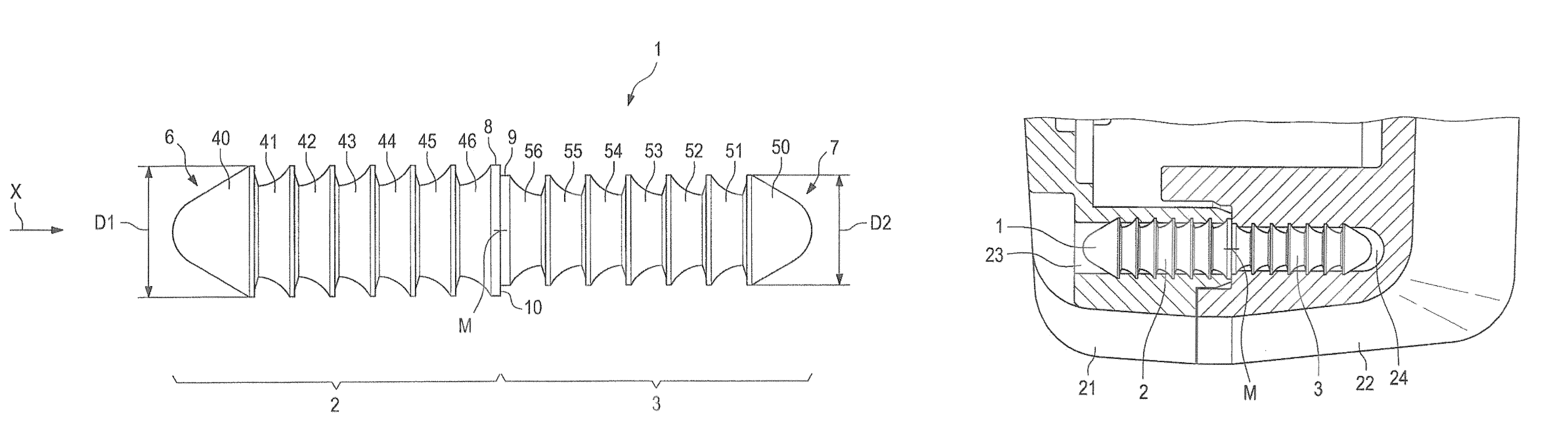
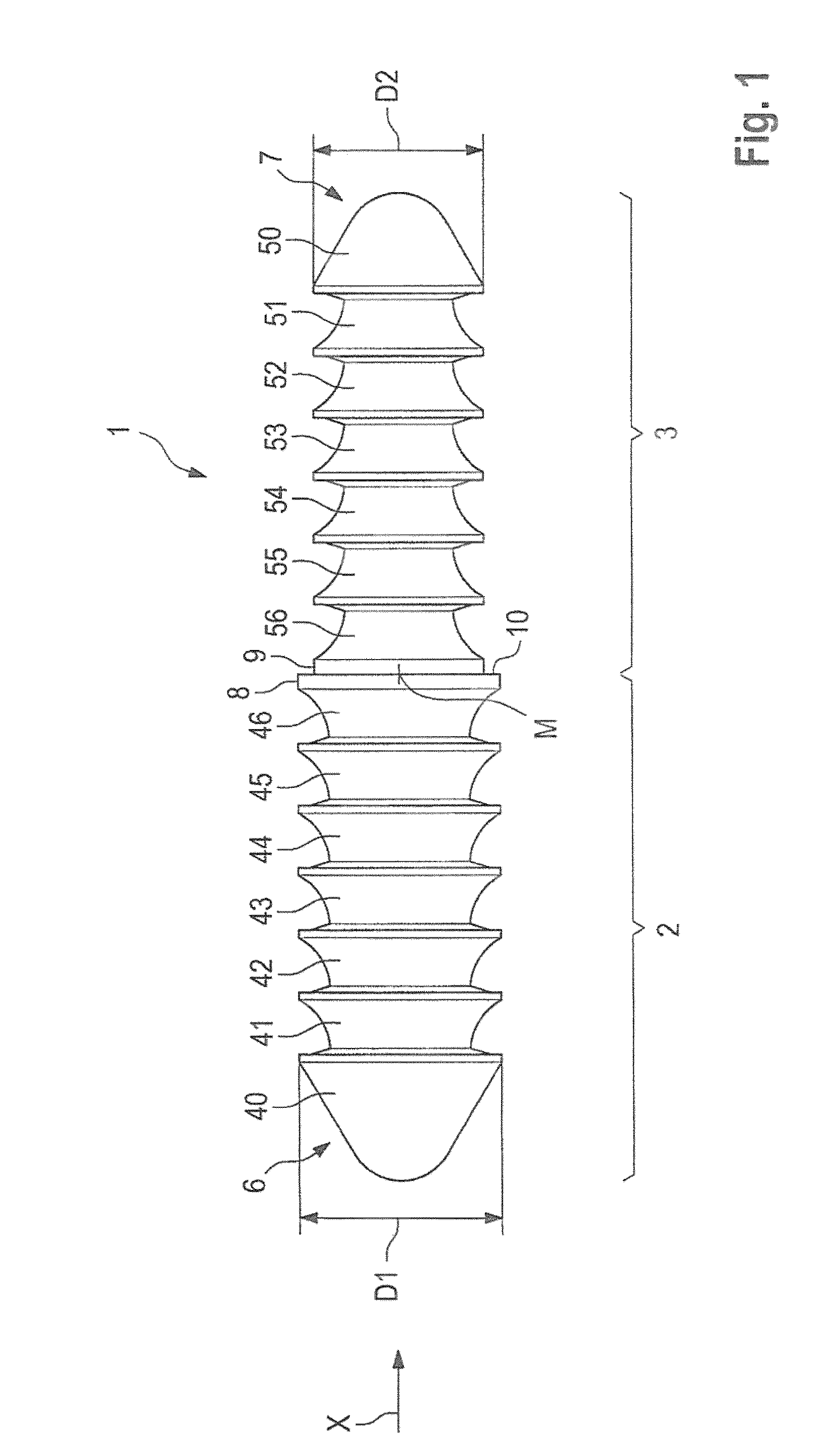
[0031]In contrast to the first embodiment according to FIG. 1, the largest diameters D2 of the ramp-like portions of the second half 3 are equally large as the largest diameter D1 of the ramp-like portions of the first half 2.

[0032]The connecting member 1 exhibits conical free ends with rounded points.

[0033]As diameters D1, D2 are of the same size, no step is formed at center M but a uniform central section 60. This section may have a larger outer diameter than diameters D1 and D2 of the ramp portions of the first and / or second half and thus serve as stop for setting the insertion depth, facilitating connection and also causing self-adjustment. Hence, the parts to be connected into which the connecting member 1 is inserted always meet in a form-locking manner at the central section 60 of the connecting member 1 making use of the central section 60.

[0034]The ramp portions do no longer continuously widen as shown in FIG. 1 but comprise two sections identified by way of example in ramp...

second embodiment

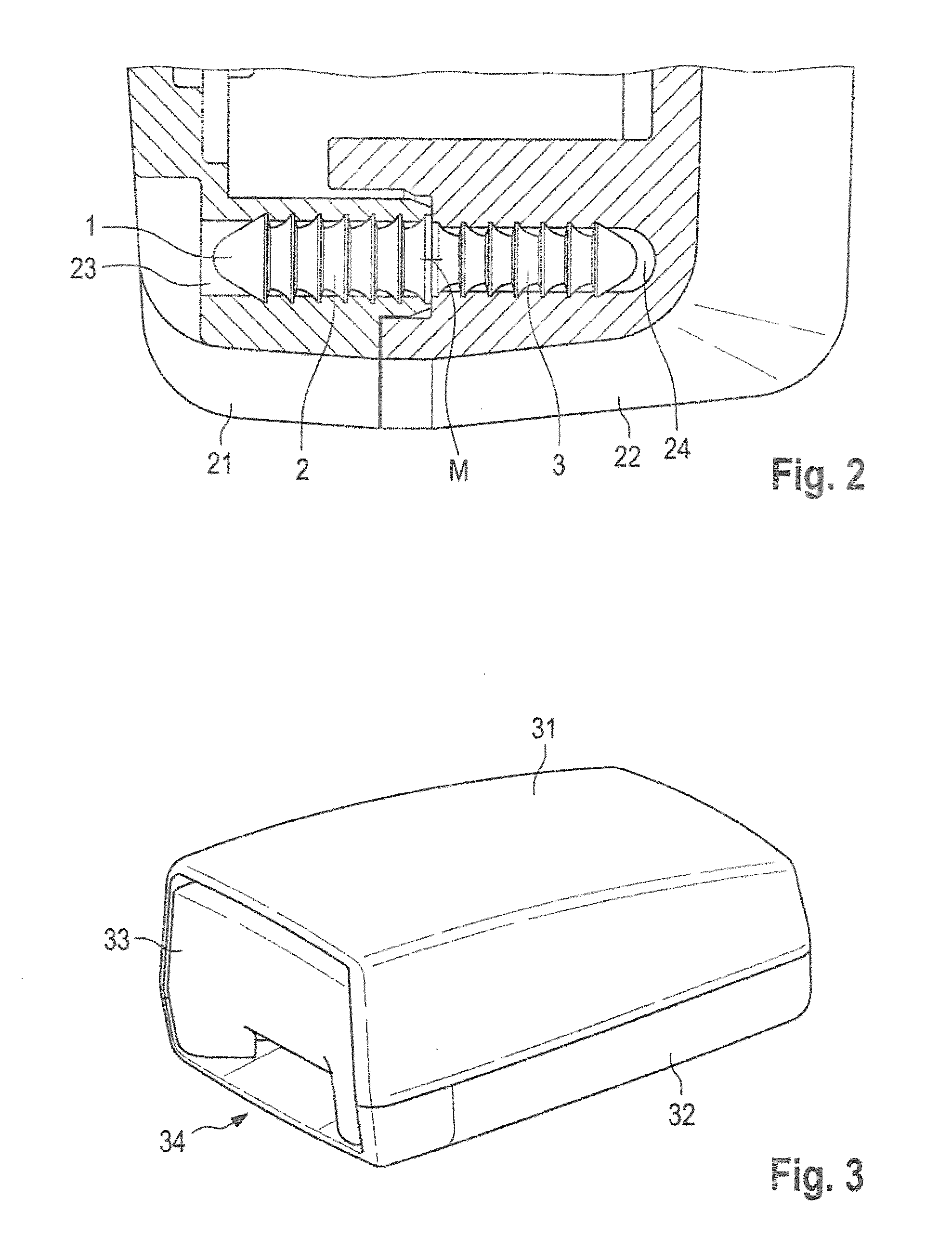
[0035]FIG. 5 is a sectional view of a housing comprising a first part 21 and a second part 22 connected by means of an inventive connecting member 1 shown in FIG. 4. This embodiment of the connection basically corresponds to that of FIG. 2, the connecting member 1 now having identical outer diameters D1 and D2 (cf. FIG. 4). Here, the central section 60 now serves as stop for one or both housing parts 21 and 22. So as to achieve a form-locking connection, a recess 61 is provided in at least one housing part 21, 22 which is deep enough to at least receive half of the central section 60. Advantageously, the recess 61 may, on one side or on both sides (i.e. either in housing part 21 or in housing part 22 or in both housing parts), be slightly deeper than half or the entire thickness of the central section 60.


PUM

PropertyMeasurementUnit
Fractionaaaaaaaaaa
Diameteraaaaaaaaaa
Shapeaaaaaaaaaa

Abstract

A connecting member for two parts includes a first half (2) and a second half (3) meeting at a center (M) of the connecting member (1). The first half (2) includes a first number of ramp portions (41-45) widening toward center (M) in an axial direction (X) thereof. The second half (3) includes a second number of ramp portions (51-55) widening toward center (M) in an axial direction (X) thereof so that the first half (2) and the second half (3) have opposite toothing.

Description

FIELD OF THE INVENTION[0001]The present invention relates to a connecting member for parts, in particular for plastic parts of a seat belt buckle, and to a method of connecting two parts by means of a connecting member.BACKGROUND OF THE INVENTION[0002]A wide variety of connecting techniques is used for connecting two parts, for instance two shells of a plastic housing. Techniques known in the art include, for instance, ultrasound techniques or friction welding methods. These methods, however, are relatively complex and require considerable technology and equipment for producing the desired connection.SUMMARY OF THE INVENTION[0003]It is an object of the present invention to provide a simplified connection for two parts to be connected.[0004]The present invention provides a connecting member for parts, in particular plastic parts, allowing for simple and secure mounting of two parts. To this end, the connecting member comprises a first half and a second half meeting at a center of the...

Claims


Application Information

Patent Timeline
IPC IPC(8): F16B19/00
CPCF16B21/082Y10T29/49826A44B11/2546
Inventor SCHUECH, ANDREAHAAS, PETER
Owner TRW AUTOMOTIVE GMBH
Why Eureka
Try Eureka