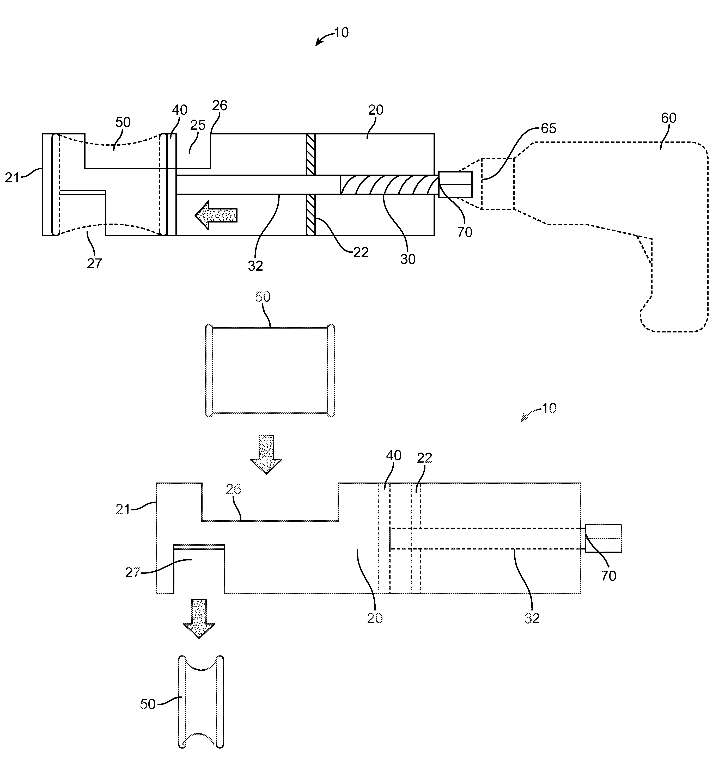
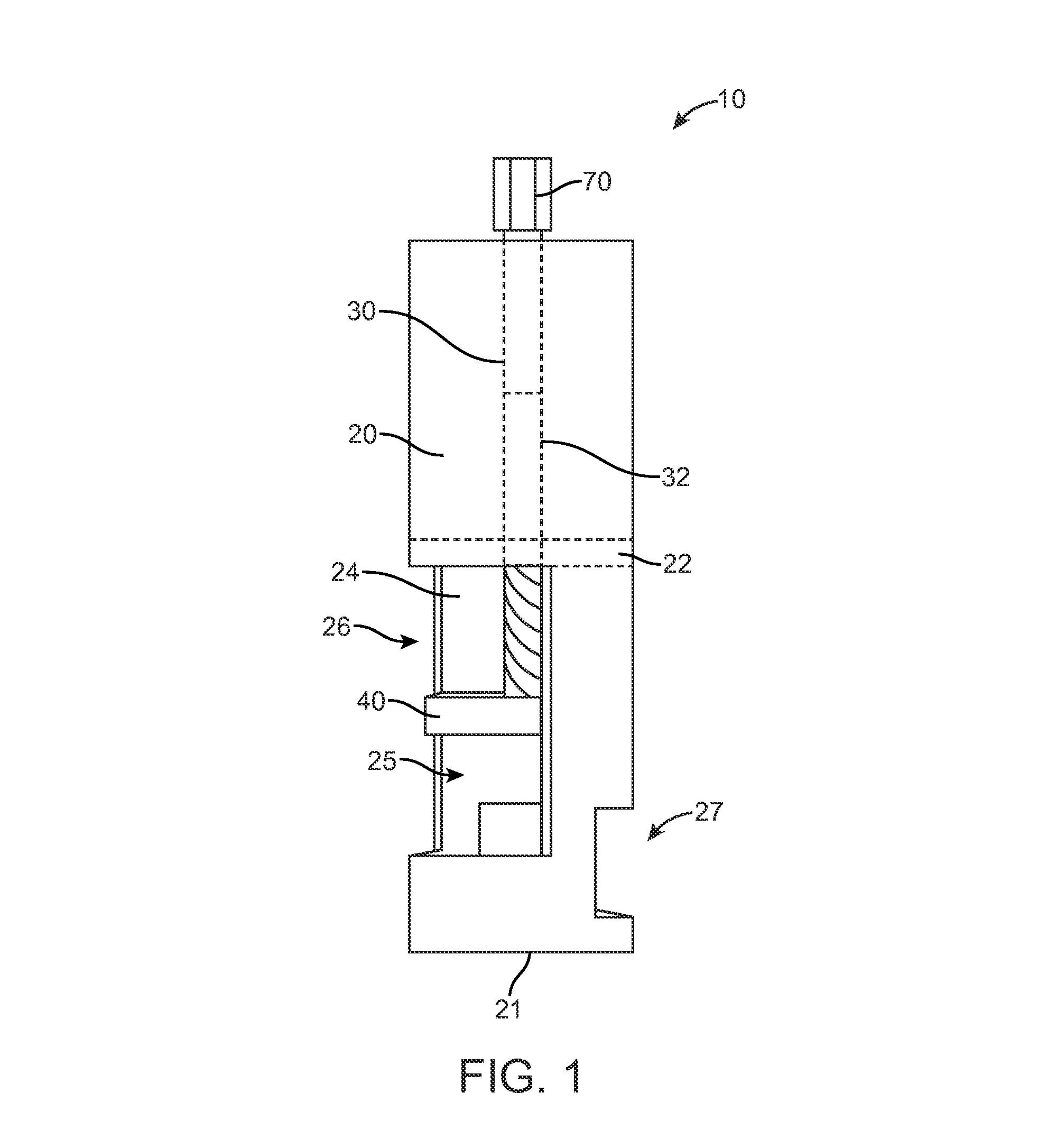
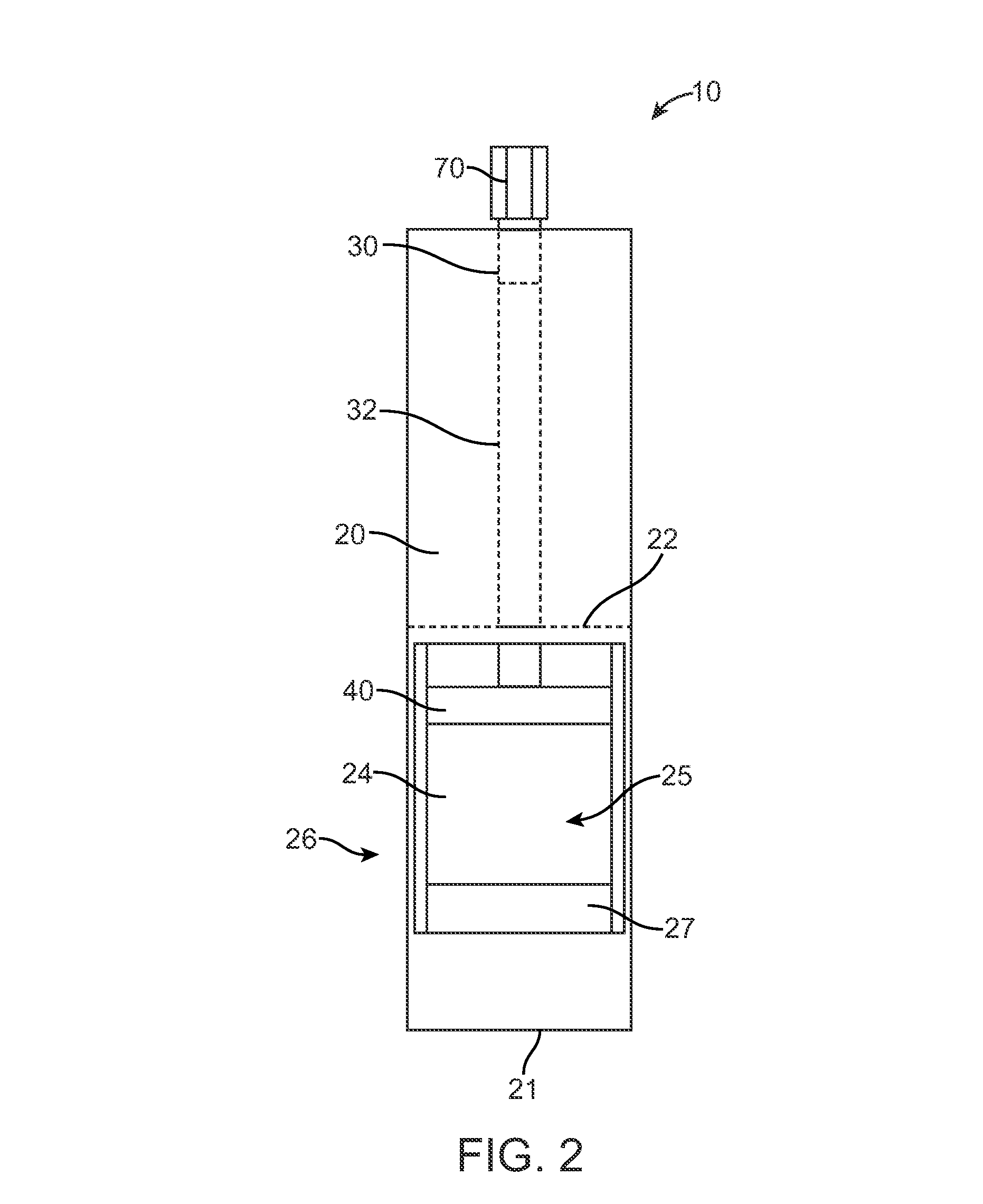
Power drill operated can crusher
- Summary
- Abstract
- Description
- Claims
- Application Information
AI Technical Summary
Benefits of technology
Problems solved by technology
Method used
Image

Examples
Embodiment Construction
[0040]The best mode for carrying out the invention is presented in terms of its preferred embodiment, herein depicted within FIGS. 1 through 6. However, the invention is not limited to the described embodiment and a person skilled in the art will appreciate that many other embodiments of the invention are possible without deviating from the basic concept of the invention, and that any such work around will also fall under scope of this invention. It is envisioned that other styles and configurations of the present invention can be easily incorporated into the teachings of the present invention, and only one particular configuration shall be shown and described for purposes of clarity and disclosure and not by way of limitation of scope.
[0041]The terms “a” and “an” herein do not denote a limitation of quantity, but rather denote the presence of at least one of the referenced items.
[0042]The present invention describes an apparatus and method that provides a means for a user to operab...
PUM
 Abstract
Description
Claims
Application Information
 - Generate Ideas
- Intellectual Property
- Life Sciences
- Materials
- Tech Scout
- Unparalleled Data Quality
- Higher Quality Content
- 60% Fewer Hallucinations
Browse by: Latest US Patents, China's latest patents, Technical Efficacy Thesaurus, Application Domain, Technology Topic, Popular Technical Reports.
© 2025 PatSnap. All rights reserved.Legal|Privacy policy|Modern Slavery Act Transparency Statement|Sitemap|About US| Contact US: help@patsnap.com