
Stun gun with knuckle guard

a technology of knuckle guard and stun gun, which is applied in the direction of knuckle guard, white arms/cold weapons, weapons, etc., can solve the problems of easy dislodgment from the user's hand, uncontrollable spasm, and inability to control the assailant, so as to achieve the effect of easy gripping with the user's fingers and easy dislodgment of the stun gun

Active Publication Date: 2013-08-27
JAGUAR IMPORTS
View PDF3 Cites 2 Cited by
  • Summary
  • Abstract
  • Description
  • Claims
  • Application Information

AI Technical Summary

Benefits of technology

[0008]In a particular embodiment, a stun gun with a knuckle guard is disclosed. The stun gun is configured to fit and be held firmly within a palm of a user's hand and easily gripped with the user's fingers. A trigger is disposed on a front portion of the housing, where the trigger causes the stun gun to discharge an electric shock through electrodes mounted above the knuckle guard to stun an assailant. The knuckle guard is configured and placed on the stun gun to cover the user's middle finger (or other finger) when the stun gun is being gripped by the user's hand. The knuckle guard protects the user's finger and prevents the assailant from easily dislodging the stun gun from the user's hand. In addition, in a struggle with the assailant, the user can punch at the assailant while the user's finger can remain firmly on the trigger and continue to depress the trigger to repeatedly shock the assailant. Further, a rear portion of the housing includes a pair of pointed projections that can be used in a downward stabbing motion as further protection from an assailant if the electric shock is ineffective.

Problems solved by technology

The electrical discharge causes the assailant's muscles to uncontrollably spasm so that the assailant is temporarily paralyzed.
A shortcoming of the prior art stun guns is that they may be dislodged from a user's hand easily when attempting to use in self-defense.
Another shortcoming of the prior art is that the stun gun may be needed in dark and desolate areas such as a parking lot at night, for example, making it difficult to orientate and activate the stun gun.
In addition, in a struggle with the assailant, the user can punch at the assailant while the user's finger can remain firmly on the trigger and continue to depress the trigger to repeatedly shock the assailant.

Method used


Image

  • Stun gun with knuckle guard
  • Stun gun with knuckle guard
  • Stun gun with knuckle guard

Examples


Embodiment Construction

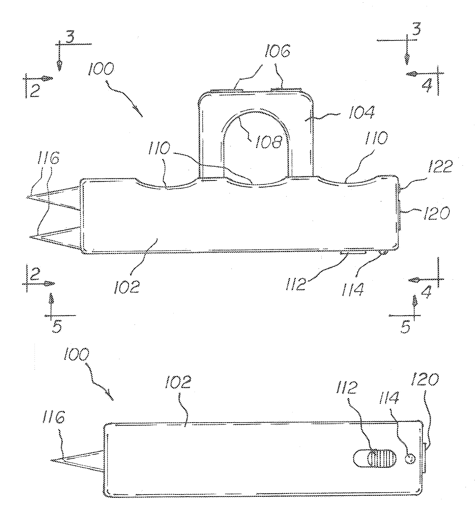
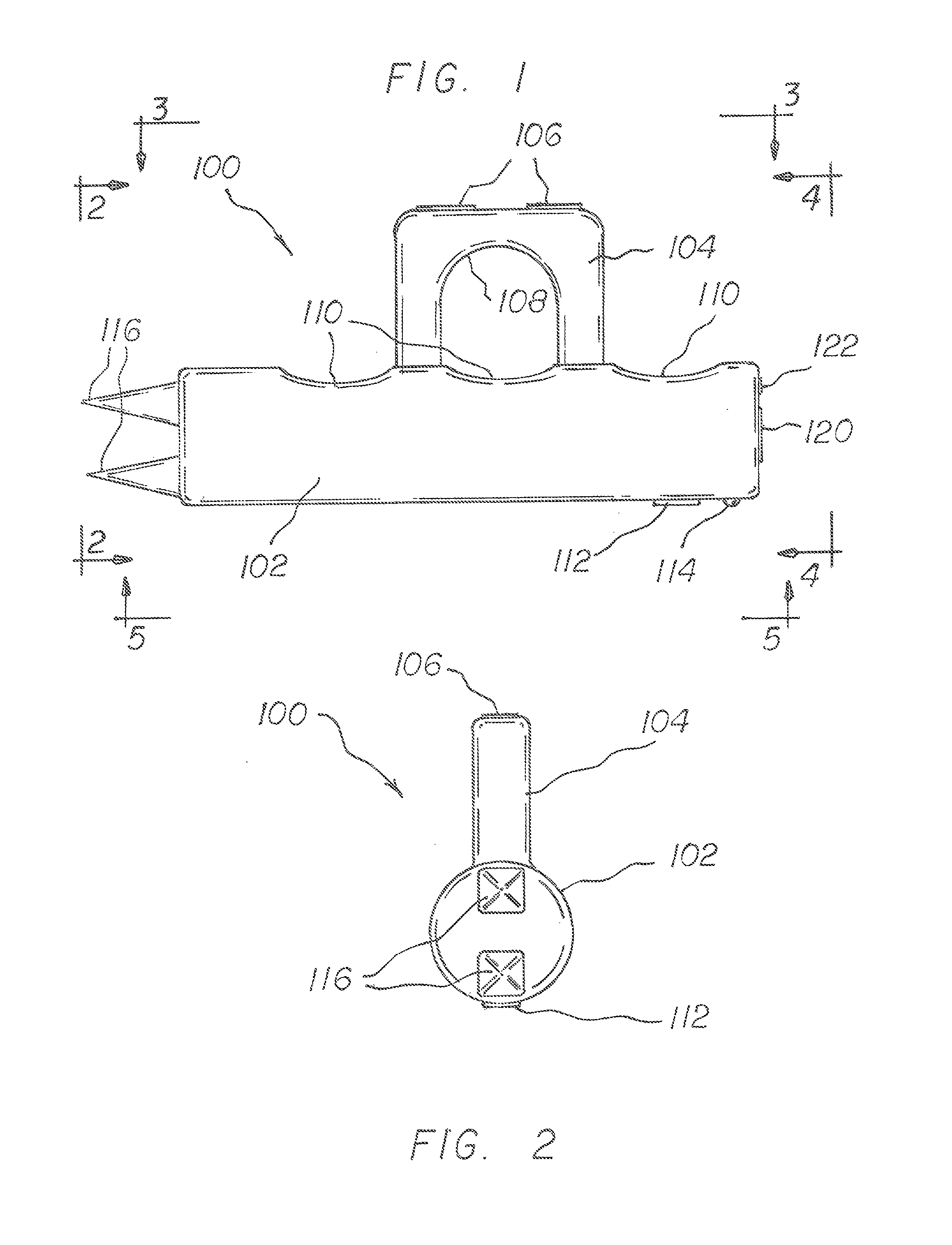
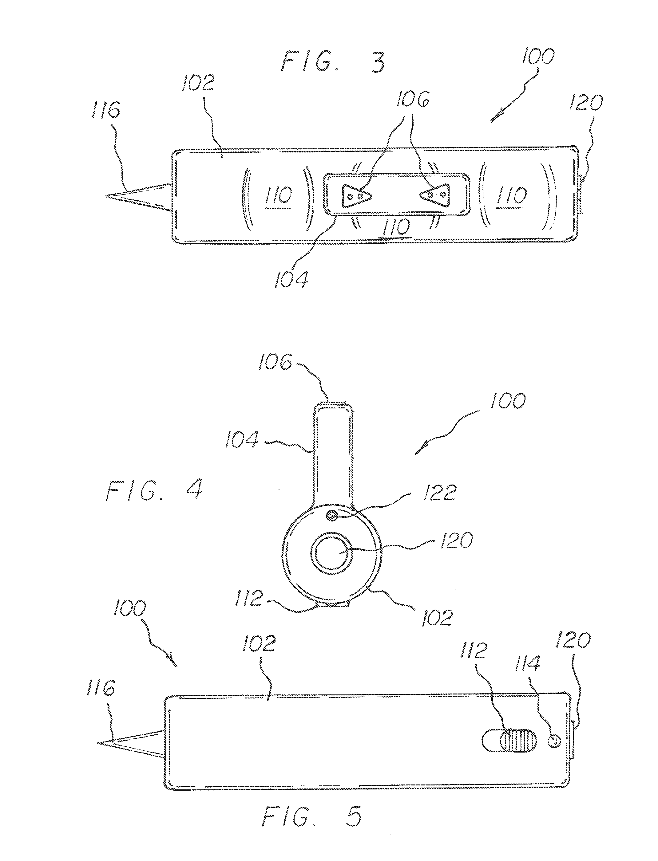
[0018]Referring now to FIG. 1, a stun gun 100 is disclosed, which includes a housing 102 that contains the electronic components for the stun gun 100 to operate. FIG. 1 is a side view of the stun gun 100 showing the finger depressions 110 that are adapted to help the user's fingers grip the stun gun 100 without slipping. In addition, the location of the stun gun electrodes 106 being directly above the user's knuckles allows the user to easily apply the electrodes 106 to the assailant in an almost punching motion that is instinctively used in self defense. In the preferred embodiment, the housing 102 is generally cylindrical in shape so that it may be held firmly within the palm of a user's hand and comfortably gripped with the user's fingers. The side of the housing 102 may include several rounded finger depressions 110 that are adapted to help the user's fingers grip the housing 102 and to provide a comfortable grip. In addition, the finger depressions 110 assist the user in orient...


PUM


Abstract

A stun gun with a knuckle guard is disclosed. The stun gun is configured to fit and be held firmly within a palm of a user's hand. A knuckle guard is disposed on the stun gun and is configured to cover the user's knuckle when the stun gun is being gripped by the user's hand. In addition, the stun gun includes a trigger that is disposed on a front portion of the housing and is used to activate the stun gun by pushing down on the trigger with the user's finger. Electrodes are mounted above the knuckle guard and are adapted to discharge an electric shock when the trigger is activated. A rear portion of the stun gun also includes a pair of pointed projections that are adapted to be used to strike the assailant to cause injury.

Description

I. FIELD[0001]The present invention relates generally to personal protection devices, and more specifically to a stun gun with a knuckle guard that is carried by a person to provide an electrical and paralyzing shock to an assailant.II. DESCRIPTION OF RELATED ART[0002]Stun guns use a high voltage and a low current electrical discharge to immobilize an assailant. The electrical discharge causes the assailant's muscles to uncontrollably spasm so that the assailant is temporarily paralyzed. The voltage of a stun gun typically ranges between 20,000 to 650,000 volts. Batteries serve as a power supply to electrical circuitry consisting of various electrical components. The circuitry includes a transformer that boosts the voltage in the circuit and reduces the amperage of the electrical current. A capacitor is used to build up and store an electrical charge before discharging the electrical shock through a pair of electrodes to the assailant.[0003]A shortcoming of the prior art stun guns i...

Claims


Application Information

Patent Timeline
Patent Type & Authority Patents(United States)
IPC IPC(8): H01T23/00
CPCF41B15/08F41H13/0018
Inventor NAWAZ, BABAR
Owner JAGUAR IMPORTS
Learn More