
Address learning in a layer two bridging network

a layer two, address learning technology, applied in the field of electronic computer networks, can solve the problem that the address information of the layer two network may be leaked between the components of the routing instance in a constrained manner, and achieve the effect of increasing the data forwarding ra

Inactive Publication Date: 2013-08-27
JUMIPER NETWORKS INC
View PDF17 Cites 15 Cited by
  • Summary
  • Abstract
  • Description
  • Claims
  • Application Information

AI Technical Summary

Benefits of technology

The invention allows a network device to provide services between two L2 domains while performing all L2 network address lookups at a single point within the forwarding process. This results in increased data forwarding rates and scalability. The techniques also allow for the identification of only those hardware and software components that need to share L2 network addresses, potentially avoiding leaking all L2 network addresses to all components of the L2 switch.

Problems solved by technology

Moreover, the L2 network address information may be leaked between the components of the routing instances in a constrained manner.

Method used


Image

  • Address learning in a layer two bridging network
  • Address learning in a layer two bridging network
  • Address learning in a layer two bridging network

Examples


Embodiment Construction

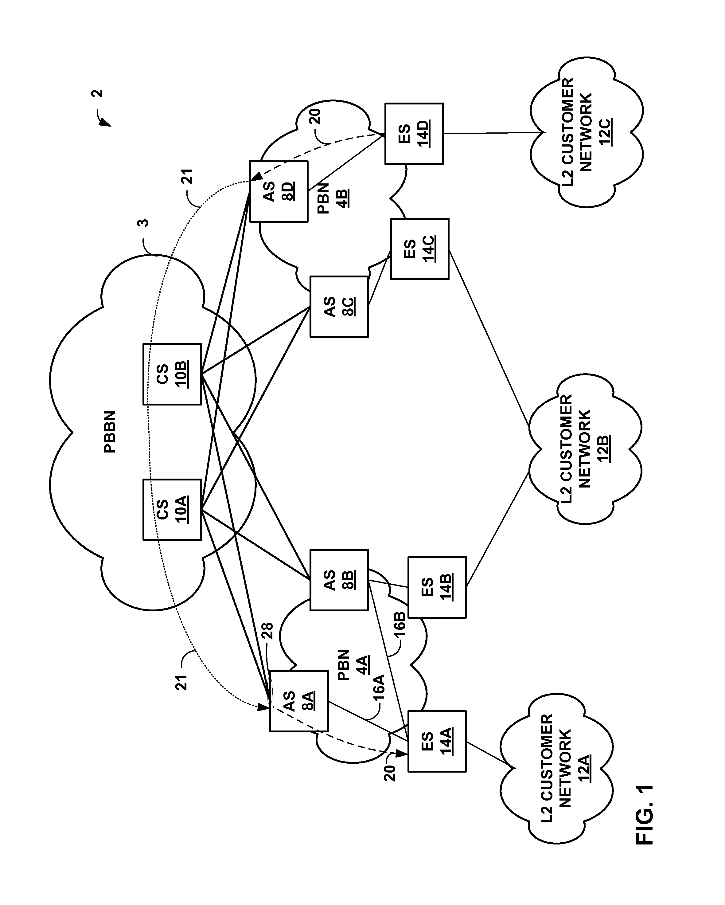
[0020]FIG. 1 is a block diagram illustrating an example network 2 in which a Provider Backbone Bridged Network (PBBN) 3 provides L2 connectivity between multiple provider bridge networks (PBN) 4A, 4B (collectively, “PBNs 4”). Each of PBNs 4 represents a component and infrastructure of a service provider that provide bridged local area network services to L2 customer networks. Each PBN 4 provides one or more service VLANs (“S-VLANS) to service and isolate L2 traffic from L2 customer networks 12. PBNs 4 may be L2 bridging networks provided by the same network service provider or by one or more different service providers.

[0021]In the example of FIG. 1, each of PBNs 4 includes one or more access switches 6 that connect the PBN to core switches within PBBN 2. In the example of FIG. 1, access switch (AS) 8A an AS 8B provide L2 connectivity to core switches (CS) 10A, 10B. Similarly, AS 8C and AS 8D provide L2 connectivity to CS 10A and CS 10B. PBBN 3 is composed of a set of Backbone Edge ...


PUM


Abstract

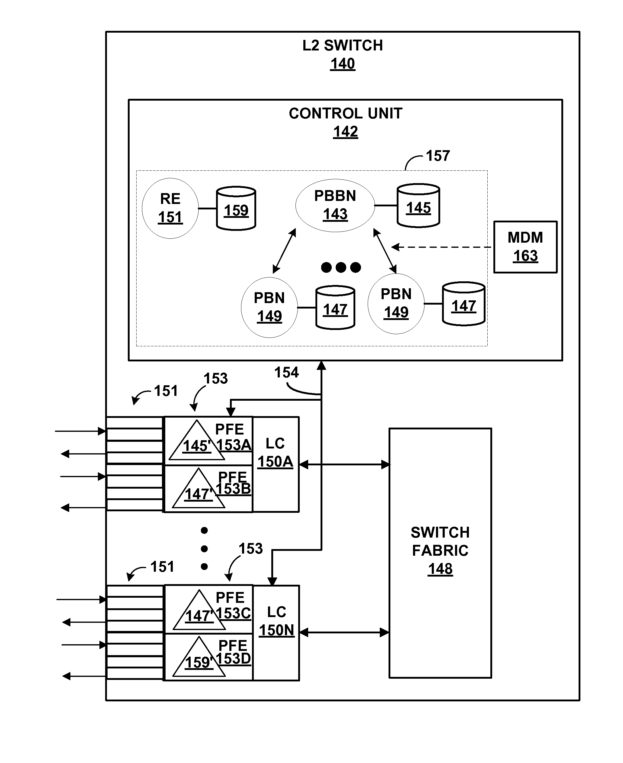
A network system includes a provider backbone bridged network (PBBN) and a multi-homed provider bridge network (PBN) having an L2 switch that operate as backboned edge bridge (BEBs) to bridge L2 packets between the PBN and the PBBN. The L2 switch executes a PBBN routing instance and a separate PBN routing instance. A plurality of packet-forwarding engine (PFE) of the L2 switch are configured to forward L2 packets between interfaces of the PBN routing instance and the PBBN routing instance. The PFEs store L2 network address tables that specify L2 network addresses reachable by the interfaces. The PFEs of the L2 switch are configured to selectively share L2 network addresses between the L2 network address tables of the PBN routing instance and the L2 network address tables of the PBBN routing instance.

Description

[0001]This application claims the benefit of U.S. Provisional Application No. 61 / 318,158, filed Mar. 26, 2010, the entire contents of which are incorporated by reference herein.TECHNICAL FIELD[0002]The invention relates to electronic computer networks and, more specifically, to layer two (L2) computer networks.BACKGROUND[0003]Networks that primarily utilize data link layer devices are often referred to as layer two (L2) networks. A data link layer device is a device that operates within the second layer of the Open Systems Interconnection (OSI) reference model, i.e., the data link layer. One example of a common L2 networks is an Ethernet network in which end point devices (e.g., servers, printers, computers) are connected by one or more Ethernet switches. The Ethernet switches forward Ethernet frames, also referred to as L2 communications or L2 packets to devices within the network. As the Ethernet switches forward the Ethernet frames the Ethernet switches learn L2 state information...

Claims


Application Information

Patent Timeline
Patent Type & Authority Patents(United States)
IPC IPC(8): H04L12/28
CPCH04L12/4662H04L12/4658
Inventor DOSHI, SANJIVBISWAL, ISWARMEHTA, KUMARGRANDHI, JAGADISH
Owner JUMIPER NETWORKS INC
Learn More