Wireless transceiver test bed system and method

a test bed and transceiver technology, applied in the direction of receiver monitoring, transmission monitoring, line-transmission details, etc., can solve the problems of inability to move uut to the field environment, inability to model wideband rf effects, and inability to model real-time effects

Active Publication Date: 2013-08-27
PARSONS CORPROATION
View PDF18 Cites 6 Cited by
  • Summary
  • Abstract
  • Description
  • Claims
  • Application Information

AI Technical Summary

Benefits of technology

[0060]The present disclosure is directed to a system and method for testing wireless transceivers in the laboratory where the advantages of laboratory testing are maintained plus many unique attributes of comprehensive field testing are made possible. Laboratory testing approaches fall into two general categories: those that use RF cable-interconnected UUT and test equipment, and those that perform computer simulations and rely on software-based UUT and RF environment models. Laboratory testing advantages include simplicity, cost effectiveness, flexibility in number and type of UUT, scalability with respect to computer resources, and ease of collaboration as networked computers may distribute and share processing and results. Shortcoming include realism and flexibility of the wireless channel, the potential inability to model any real time effects (such as if the simulation software cannot run in real time), inability to move UUT to field environment, and inability to model wideband RF effects.
[0061]The present disclosure describes a novel system and new methods to allow laboratory-based testing to overcome these shortcomings. These innovations apply to both the RF cable-interconnected laboratory approach, and the software model-based approach. In both cases, a Virtual Wireless Channel (VWC) function is introduced that flexibly and accurately allows the wireless channel to be modeled and exercised. The UUT is interfaced to the VWC using down / up converted digital RF samples to allow all significant RF channel effects to be modeled including multipath and real time radio wave propagation. The modeling of the real time effects is facilitated by the introduction of executing the test in piecewise real time or real time capable hardware, and using metadata which is communicated between the UUT and VWC. The metadata contains the information needed by the test architecture components to reference the down / up converted digital RF to the true RF spectrum as well as the geographic lay down of the RF emitters in the defined for the test scenario. This is enabled by time tags for samples being included in the metadata, and controlling delay through the VWC using the sample time tags. The metadata allows the UUT and VWC to operate in a wideband RF sense. The metadata may include time stamp information, location information, or frequency information including center frequency, bandwidth, power and modulation. Primary Users, Secondary Users and other interference (Virtual Spectrum Users (VSU)) can be created and accurately emulated in the VWC to create the realistic RF environment. The VSU may have selectable transmission parameters and selectable physical characteristics. For example, transmission parameters may include frequency, bandwidth, power, modulation. Physical characteristics may include location, speed, direction of motion, and antenna parameters including type, elevation gain, azimuth gain, phase, polarization and orientation. The VSU can be selected to be a transmitter only, a transceiver or a transceiver. The VSU can be selected to be a communication device, a sensor such as a radar, a navigation device, or a jammer and can be the same type or different than the UUT.

Problems solved by technology

Shortcoming include realism and flexibility of the wireless channel, the potential inability to model any real time effects (such as if the simulation software cannot run in real time), inability to move UUT to field environment, and inability to model wideband RF effects.
Further, the Carnegie Mellon testbed lacks the ability to use specific geographic location data such as digital terrain and morphology to emulate RF path conditions necessary for accurate RF environment emulation in a manner similar to the present disclosure.

Method used


Image

  • Wireless transceiver test bed system and method
  • Wireless transceiver test bed system and method
  • Wireless transceiver test bed system and method

Examples


Embodiment Construction

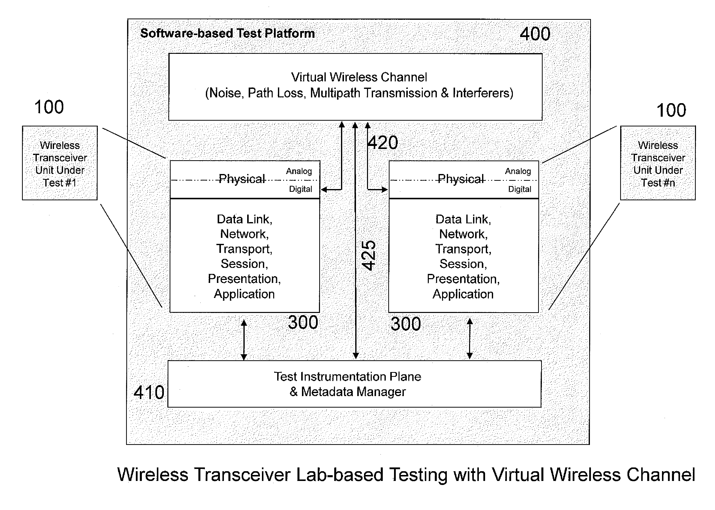
[0076]The present disclosure describes a system and method for testing wireless transceivers in the laboratory where the advantages of laboratory testing are maintained plus many unique attributes of comprehensive field testing are made possible. Two embodiments of the disclosure will be described to illustrate the system and method concepts.

[0077]As previously described, two prior art laboratory test bed approaches exist. The first uses a computer hardware and software platform to host a software model-based test bed application for wireless transceivers as illustrated in FIG. 3c. As described previously, this approach includes as its advantages simplicity, cost effectiveness, flexibility in number and type of UUT, scalability with respect to computer resources and ease of collaboration as networked computers may distribute and share processing and results. The shortcoming of the approach include realism and flexibility of the wireless channel, the potential inability to model any ...


PUM


Abstract

A system and method for testing wireless transceivers in a virtual wireless environment including emulating an RF environment, creating virtual spectrum users having selectable transmission parameters and physical characteristics and evaluating the operation of the wireless transceiver in the virtual wireless environment.

Description

[0001]The present disclosure relates to the field of functional and performance testing of wireless transceivers. More specifically, this disclosure describes a system and method for testing wireless transceivers in the laboratory where the advantages of laboratory testing are maintained plus many unique attributes of comprehensive field testing are made possible.BACKGROUND[0002]In the process of developing, certifying and deploying wireless transceivers such as communications devices, it is necessary to test performance at various points along the way. This testing can be both to assure that the communications system meets its intended purpose and performance, and to be sure it does not interfere with other wireless devices that share the RF spectrum.[0003]The criticality of this testing process is well illustrated by the activities in the cognitive radio (CR) technology area. Cognitive Radios are wireless transceivers that sense spectrum usage by primary users (PU), and adapt thei...

Claims


Application Information

Patent Timeline
Patent Type & Authority Patents(United States)
IPC IPC(8): H04B17/00
CPCH04W24/00H04B17/391H04B17/20H04B17/10H04B17/0085
Inventor KENNEDY, JOSEPHCARLSON, JOHN
Owner PARSONS CORPROATION
Why Eureka
Try Eureka