Supercharge Your Innovation With Domain-Expert AI Agents!

Landing system for well casing

a well casing and well casing technology, applied in the direction of fluid removal, sealing/packing, borehole/well accessories, etc., can solve the problems of time-consuming removal of the blowout preventer stack, high cost, and high cost of rig tim

Active Publication Date: 2013-09-03
MILLER DAVID M
View PDF4 Cites 0 Cited by
  • Summary
  • Abstract
  • Description
  • Claims
  • Application Information

AI Technical Summary

Benefits of technology

The patent describes a method and apparatus for landing a string of casing joints in a hydrocarbon well without the need to lock the top of the casing into a wellhead or remove and reinstall a blowout preventer stack. A hanger is attached to the last joint of the string run into the well and is landed onto a load shoulder or other structure installed within or upon the uppermost joint of the previously installed string of casing outside of the string being installed. The hanger allows for controllable longitudinal shortening of hanger length, which removes exertion of casing weight on the hanger. This reduces the likelihood of damage to the casing during installation and reduces the need for costly and time-consuming well construction measures.

Problems solved by technology

Removal of the blowout preventer stack is time consuming, and requires a drilling rig to sit idle for hours while the stack is removed, the casing spool or wellhead attached, and the blowout preventers nippled back up.
Because of the relatively high expense for rig time, this delay is expensive.
These devices are usually expensive and add substantially to the expense of the well.

Method used


Image

  • Landing system for well casing
  • Landing system for well casing
  • Landing system for well casing

Examples


Embodiment Construction

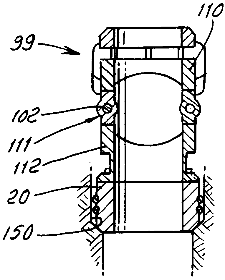
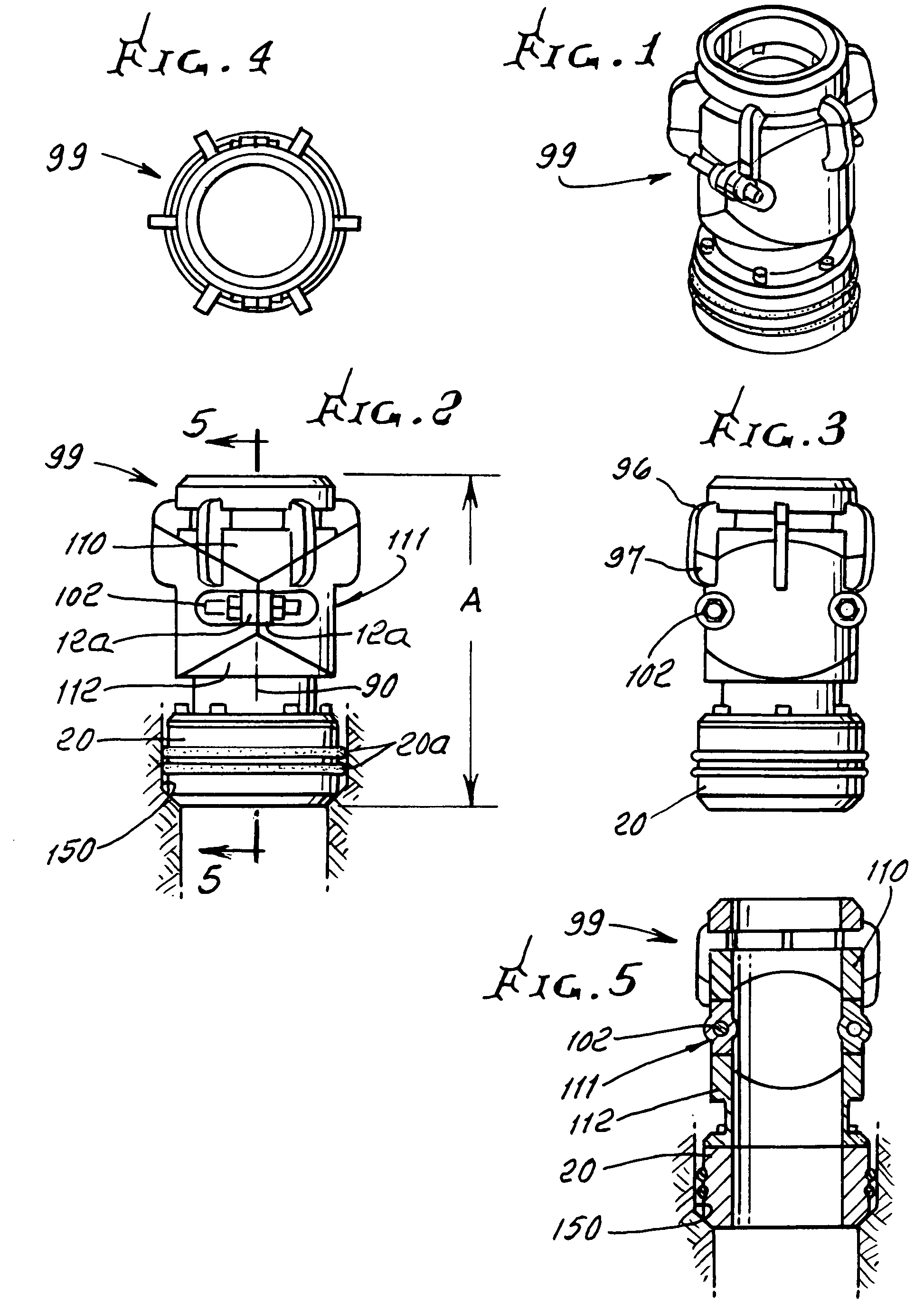
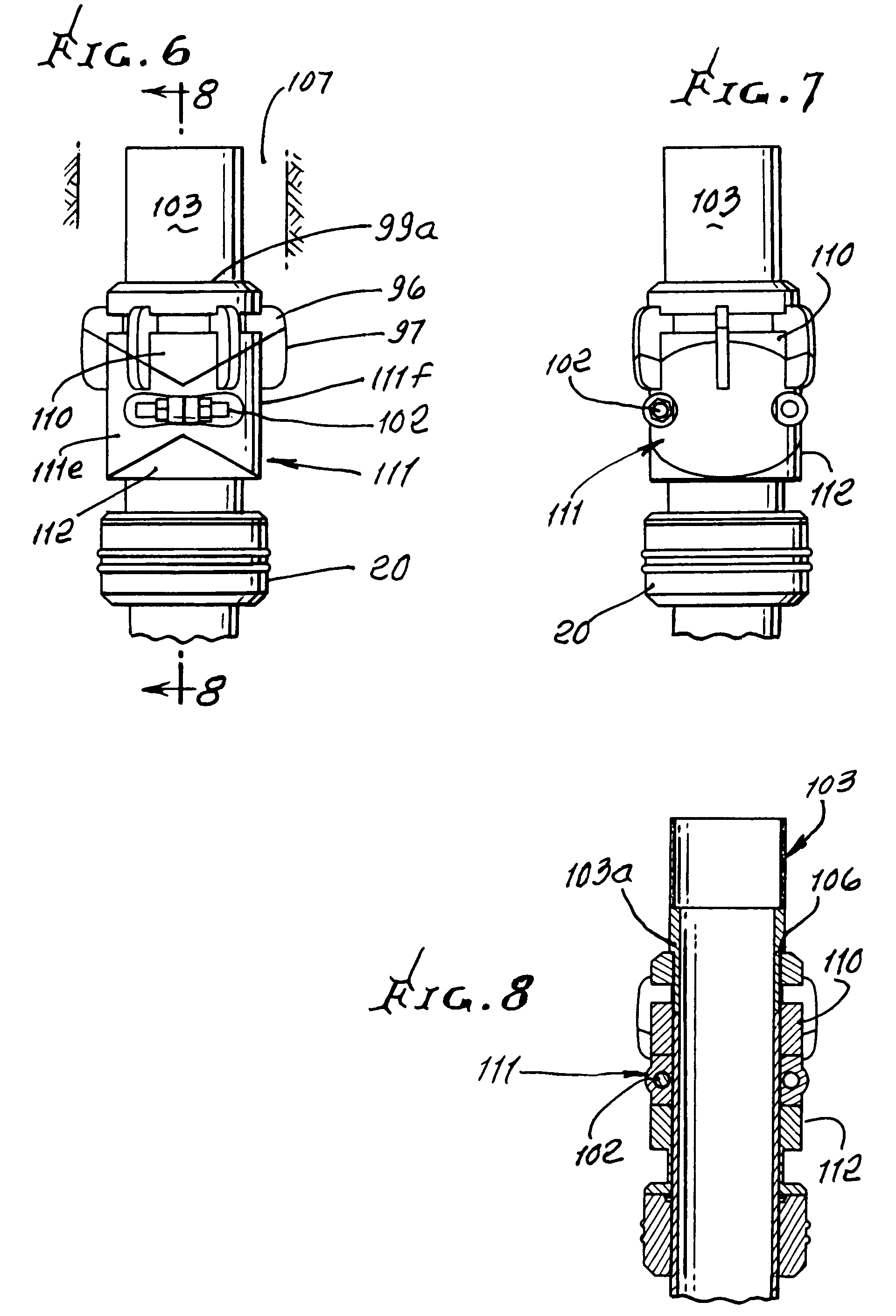
[0077]Referring first to FIGS. 6 and 26, they show hanger 99 upper, lower and intermediate members 110, 111 and 112 prior to (FIG. 6) and after (FIG. 26) lateral translation or expansion of intermediate member 112 relative to upper and lower members 110 and 111. Simplified schematic view 26′ corresponds to FIG. 26. Such lateral translation is facilitated by sliding slippage of upward facing upper V-shaped wedge surfaces 111a and 111b on member 111, relative and with respect to downward facing upper V-shaped wedge surfaces 110a and 110b on 110; and simultaneous sliding slippage of downward facing lower inverted V-shaped wedge surfaces 111c and 111d relative and with respect to upward facing lower inverted V-shaped wedge surfaces 112c and 112d on 112. This enables downward bodily displacement of 110 relative to and beneath wall casing 103 flange or shoulder 103a previously landed on the top 99a of hanger 99, the casing then connected in position in the well, whereby casing loading on ...


PUM


Abstract

The method of installing a plurality of casing sections in a well, that includes providing a hanger supporting the casing sections to extend longitudinally in the well, landing the hanger on structure in the well, whereby weight of the casing sections longitudinally compresses the hanger, cementing the casing sections in position in the well, below the hanger, adjusting the hanger to provide for controllable longitudinal shortening of hanger length, thereby removing exertion of casing weight on the hanger, and removing at least part of the hanger away from the well head.

Description

[0001]This invention claims priority from provisional application Ser. No. 61 / 262,912, filed Nov. 19, 2009.BACKGROUND OF THE INVENTION[0002]This invention relates generally to methods and apparatus utilized in the completion of hydrocarbon wells, and is particularly directed to methods for reducing the amount of drillrig time and associated expense associated with hanging casing or tubing within a previously installed concentric outer casing.[0003]A hydrocarbon well typically employs a plurality of tubular or concentric casing strings extended from the ground surface toward the subsurface hydrocarbon reservoir, with the outermost string having the largest diameter and being the shortest in length, with each inner string having a smaller diameter and a longer length. The outermost pipe, the conductor pipe, is installed as part of site preparation and will be present when the drilling rig moves onto the location. The conductor pipe typically extends from a depth of 20 to 100 feet, and...

Claims


Application Information

Patent Timeline
Patent Type & Authority Patents(United States)
IPC IPC(8): E21B23/02
CPCE21B33/04
Inventor MILLER
Owner MILLER DAVID M
Features
  • R&D
  • Intellectual Property
  • Life Sciences
  • Materials
  • Tech Scout
  • Unparalleled Data Quality
  • Higher Quality Content
  • 60% Fewer Hallucinations
Learn More