Lamp powering technology

a technology of powering technology and street lamps, which is applied in the direction of electric variable regulation, process and machine control, instruments, etc., can solve the problems of not being able to sustain lighting for three continuous rainy days, and the street lamps that are arrayed with such solar powered street lamps are often left dark, so as to reduce the power consumption of the device, reduce the available energy, and reduce the effect of proportionate reduction in the luminosity of the lamp

Active Publication Date: 2013-09-03
LIGHTING TAIWAN
View PDF7 Cites 4 Cited by
  • Summary
  • Abstract
  • Description
  • Claims
  • Application Information

AI Technical Summary

Benefits of technology

[0004]At least one embodiment described herein relates to a devise for channeling electricity from an electrical energy source to a lamp when the lamp is consuming electricity, and when doing so adjusts downwards the amount of power channeled to the lamp as a function of available energy in the electrical energy source. In so doing, a reduction in the available energy in the electrical energy source causes a less proportionate reduction in luminosity of the lamp. This might be accomplished by passing the electricity through a passive network of resistors and diodes on its way from the electrical energy source to the lamp, which reduces the power consumption by the device. In one example, the electrical energy source may be a battery that is powered by one or more solar panels. In that case, the device may also channel electricity from the solar panel(s) to the battery.

Problems solved by technology

However, existing commercial solar powered street lamps are not able to sustain lighting for three continuous rainy days under certain very normal and common situations.
Accordingly, streets that are arrayed with such solar powered street lamps are often left dark.

Method used


Image

  • Lamp powering technology
  • Lamp powering technology
  • Lamp powering technology

Examples


Embodiment Construction

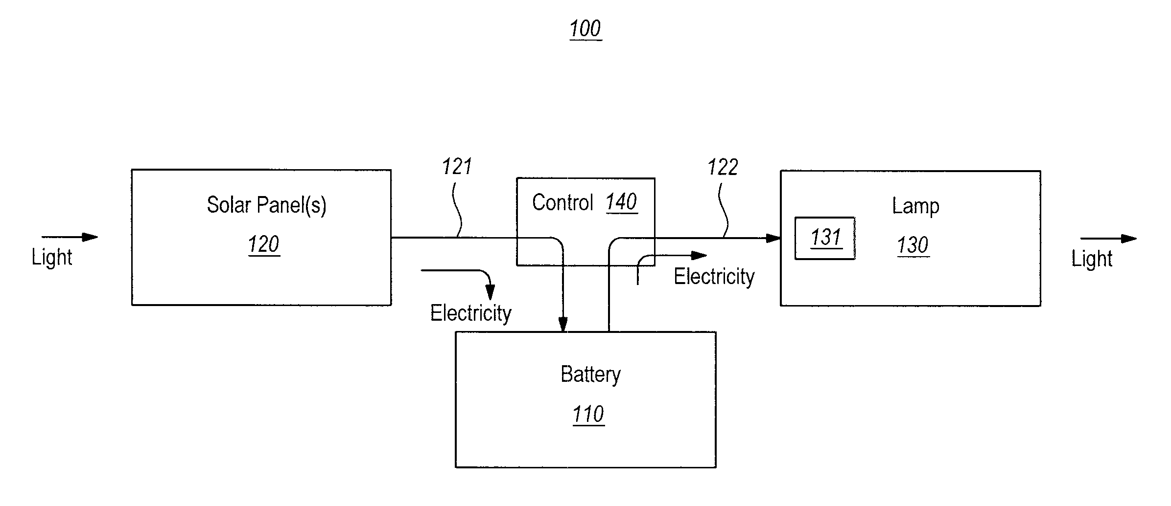
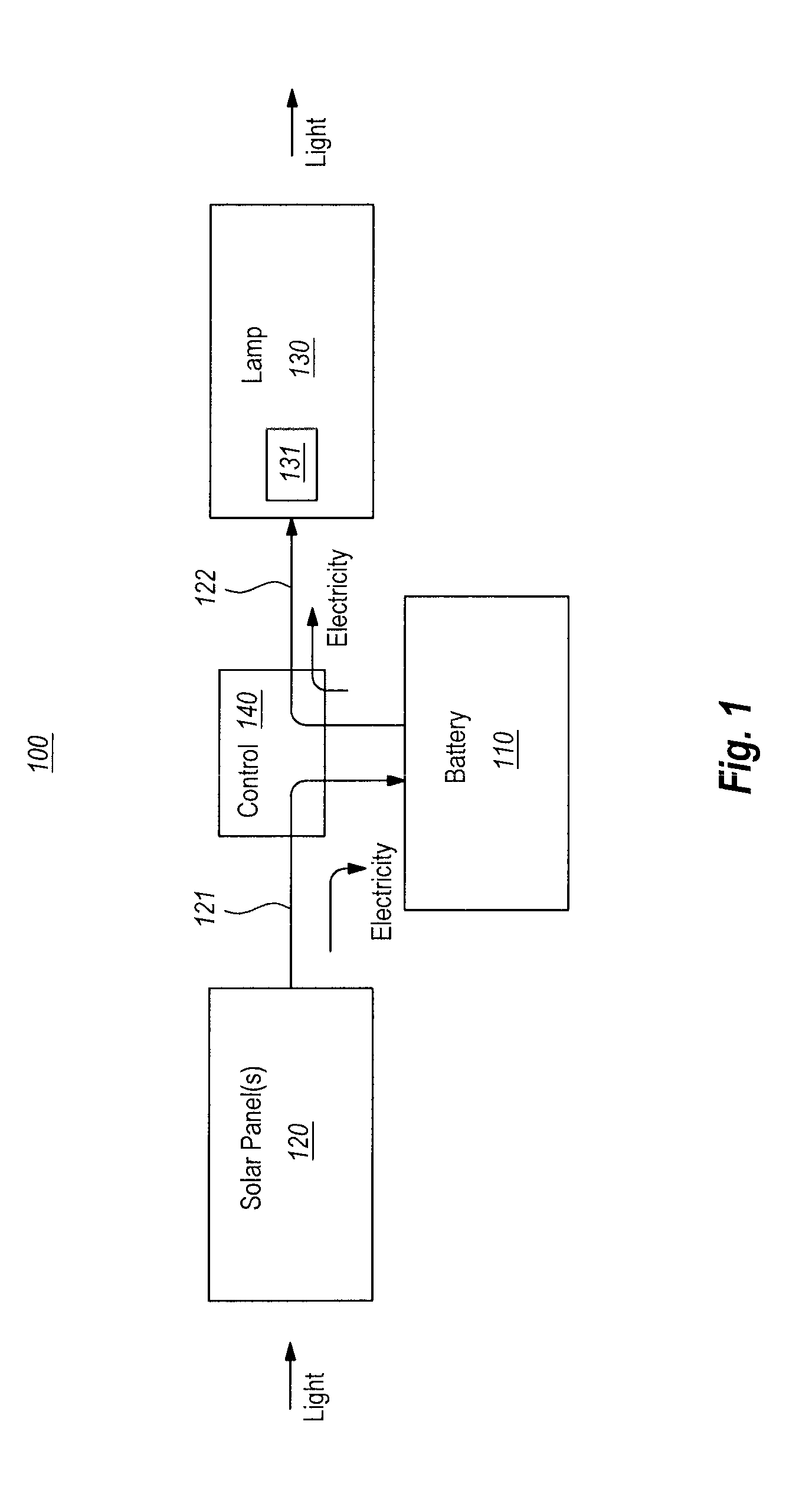
[0012]The principles described herein related to a technology for powering a lamp that potentially includes a passive network of diodes and resistors. The lamp design further includes a system control unit (such as a control box) that allows for increased lighting stamina in a longer series of continuous rain days as compared to commercial lamps even for the same given solar panel and battery.

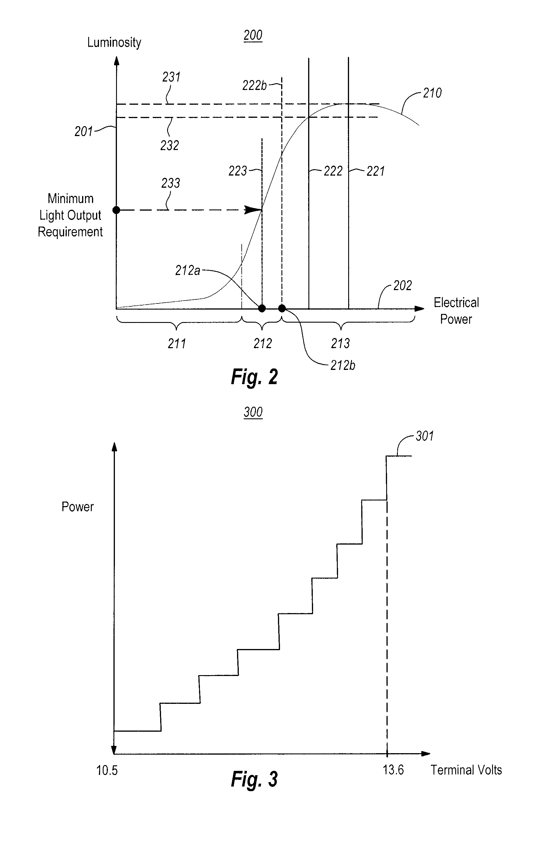
[0013]The lamp can be operated across the full range of the available stored energy in the battery. As the battery's stored energy decrease, the systems' power consumption is reduced and the system efficacy is increased, while still maintaining the lighting above the required brightness. In other words, the novel system can continuously (or step by step) improve efficacy as battery stored energy drains down.

[0014]Solar powered lamps use solar panels to charge batteries during sunny conditions (hereinafter referred to as “sunny days”) when significant numbers of sun-originated photons are incide...


PUM


Abstract

A device is designed for channeling electricity to a lamp, and adjusts downwards the amount of power channeled to the lamp as a function of available electrical energy in the source. In so doing, a reduction in the available energy in the source causes a less proportionate reduction in luminosity of the lamp. This might be accomplished by passing the electricity through a passive network of resistors and diodes on its way down to the lamp. In one example, the electrical energy source may be a battery that is powered by one or more solar panels. In that case, the device may also perform the function of protecting the battery from being overly charged. It channels downwards a greater daily lamp's energy consumption than that of daily electrical charging from the solar panels, when the available battery energy is near its full capacity.

Description

BACKGROUND[0001]Solar powered street lamps are in commercial use. Solar powered street lamps receive solar energy from the sun in the form of light. The light photons are converted into electricity by a solar panel. A battery system stores electrical energy, where it can be used during dark conditions (e.g., nighttime, or cloudy times) to power the street lamp.[0002]Conventional commercial solar powered street lamps aim to be able to provide lighting over three continuous rainy. However, existing commercial solar powered street lamps are not able to sustain lighting for three continuous rainy days under certain very normal and common situations. Accordingly, streets that are arrayed with such solar powered street lamps are often left dark.[0003]The inventors performed a study to reveal the root cause key issues for this problem; and then invent the system designs to overcome this issue; as disclosed in this patent disclosure.BRIEF SUMMARY[0004]At least one embodiment described herei...

Claims


Application Information

Patent Timeline
Patent Type & Authority Patents(United States)
IPC IPC(8): H05B37/02H05B44/00
CPCH05B33/0845H05B37/00Y02B20/341H05B45/10Y02B20/30H05B47/10H05B47/28H02J7/0063H02J7/007182H02J7/35Y02B20/72
Inventor SHUY, GEOFFREY WEN-TAILI, CHANG-HORANGLAI, HSIN-CHEN
Owner LIGHTING TAIWAN
Why Eureka
Try Eureka