Power supply device

a power supply device and power supply technology, applied in the direction of electric generator control, dynamo-electric converter control, electric generator control, etc., to achieve the effect of reducing the input torque of the magneto ac generator, reducing the operating load, and reducing the energy for rotating

Inactive Publication Date: 2013-09-03
MITSUBISHI ELECTRIC CORP
View PDF17 Cites 1 Cited by
  • Summary
  • Abstract
  • Description
  • Claims
  • Application Information

AI Technical Summary

Benefits of technology

[0006]The invention was devised to solve the problem discussed above and has an object to provide a power supply device using a magneto AC generator that is capable of reducing an input torque to the magneto AC generator by making a switching between a rectifier circuit and a short circuit at an output end of the magneto AC generator according to a operating state of a rotor or a torque supplying device to reduce a operating load on the torque supplying device and hence to reduce energy for rotating the rotor necessary for the generator, thereby achieving power generation efficiency better than that of the related art.
[0008]According to the power supply device of the invention, by switching the short circuit between the short operating mode and the rectification operating mode according to a operating state of the rotor or the torque supplying device, an input torque to the magneto generator is reduced, which makes it possible to reduce a operating load on the torque supplying device and hence to reduce energy for rotating the rotor necessary for electric power generation. It thus becomes possible to obtain a power supply device achieving power generation efficiency better than that of the related art.

Problems solved by technology

Hence, the generator in the power supply device in the related art does not necessarily generate electric power at an input torque suitable to a operating state of the rotor or the torque supplying device.

Method used


Image

  • Power supply device
  • Power supply device
  • Power supply device

Examples


first embodiment

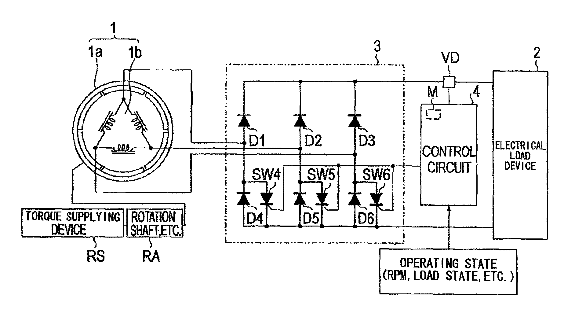
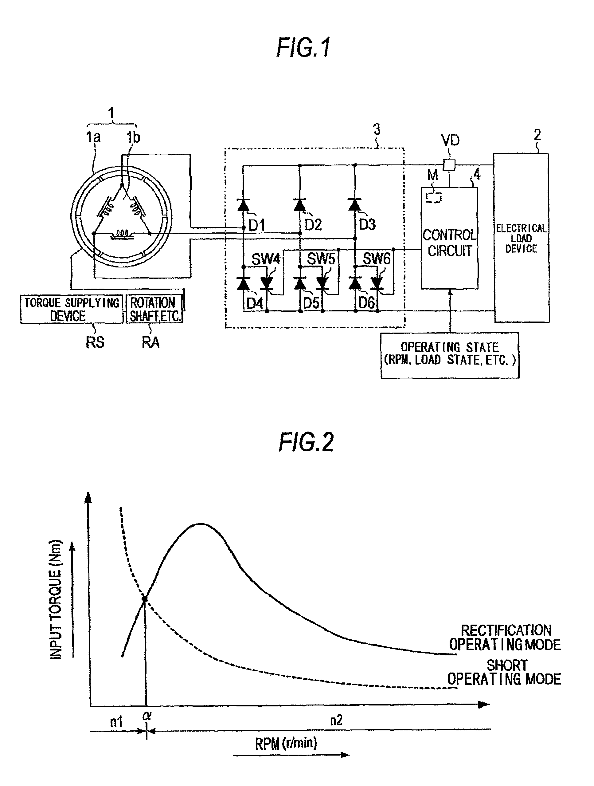
[0019]FIG. 1 is a view showing the overall configuration of a power supply device according to a first embodiment of the invention.

[0020]Referring to FIG. 1, the power supply device of the first embodiment includes a magneto (AC) generator 1, a rectifier circuit 3 that rectifies an AC generated by the magneto generator 1 to a DC, a electrical load device 2 to which electric power rectified to the DC in the rectifier circuit 3 is supplied, a voltage detection circuit VD formed of a voltmeter to find a voltage of the electrical load device 2, thyristors SW4 through SW6 provided to the rectifier circuit 3 and forming a short circuit that electrically shorts an output end of the magneto generator 1, and a control circuit 4 that controls the voltage of the electrical load device 2 to be a first set value according to the voltage detected by the voltage detection circuit VD.

[0021]The magneto generator 1 includes a rotor 1a having a magnet divided into a plurality of sections along a rotat...

second embodiment

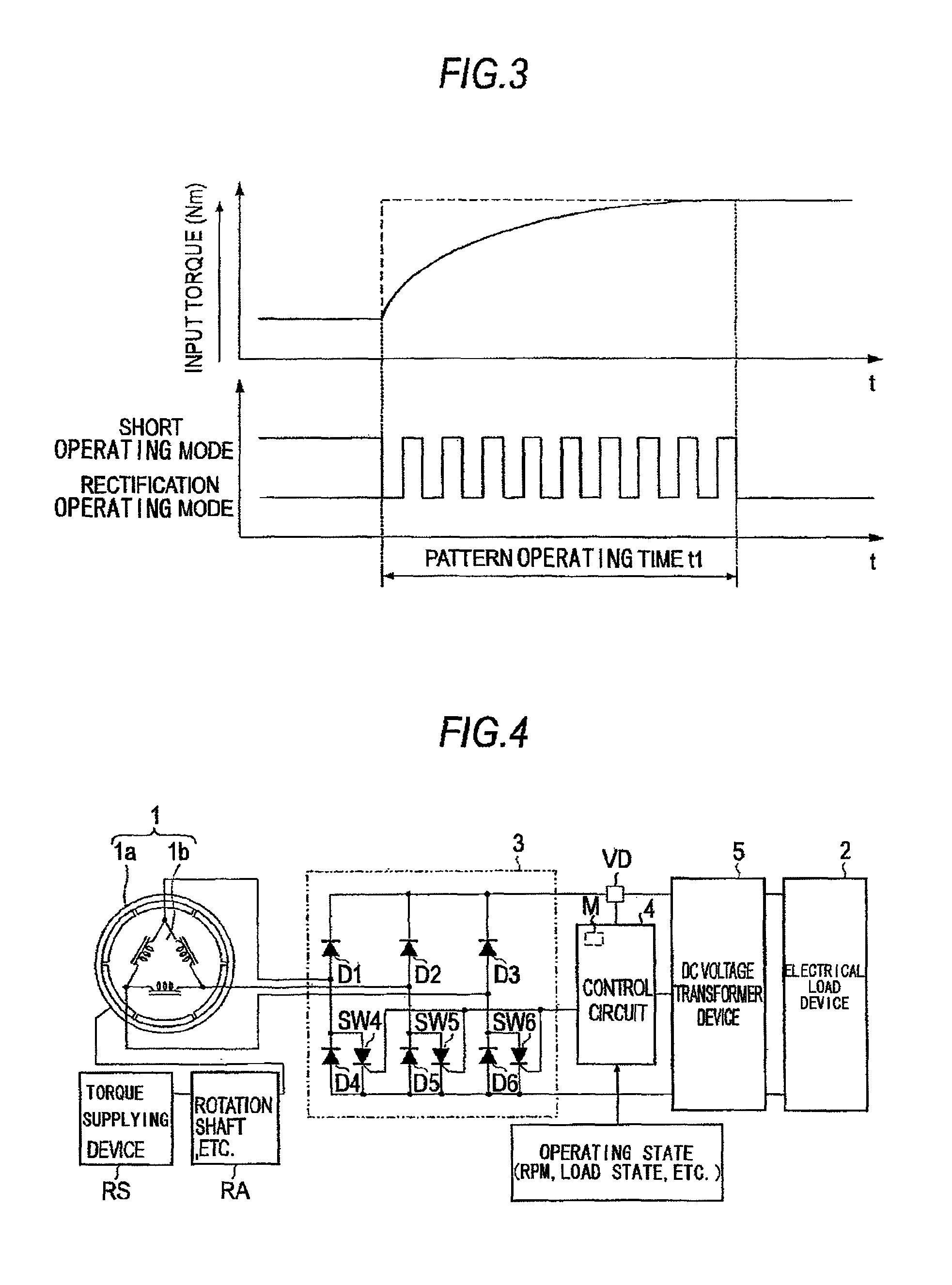
[0039]FIG. 4 is a view showing the overall configuration of a power supply device according to a second embodiment of the invention. The power supply device of the second embodiment is of the configuration same as the configuration of the first embodiment above except that a DC voltage transformer device 5 that is capable of varying a transformation ratio and transforms an output voltage of the rectifier circuit 3, Vrout, to a voltage between input terminals of the electrical load device 2, Vbin, is additionally provided.

[0040]FIG. 5 shows the characteristic of an input torque to the magneto generator 1 with respect to a rpm of the rotor 1a in the respective operating modes in the second embodiment.

[0041]An input torque to the magneto generator 1 in the rectification operating mode varies with a transformation ratio (Vbin / Vrout) of the DC voltage transformer device 5. Referring to FIG. 5, let α1 be a rpm at the intersection of an input torque in the short operating mode and an input...

third embodiment

[0047]FIG. 6 is a view showing the overall configuration of a power supply device according to a third embodiment of the invention. The power supply device of the third embodiment is of the configuration same as the configuration of the first embodiment above except that the control circuit 4 is replaced by a control circuit 4a and the thyristors SW4 through SW6 are replaced by thyristors SW4a through SW6a, which are short circuit. Herein, the control circuit 4a performs ON and OFF control independently on the respective gate signals of the thyristors SW4a through SW6a.

[0048]FIG. 7 shows the characteristic of an input torque to the magneto generator 1 with respect to timing at which a switching is made between the short operating mode and the rectification operating mode in the respective thyristors (short circuits) SW4a, SW5a, and SW6a of the third embodiment.

[0049]As is shown in FIG. 7, a switching time is provided to the timing at which the respective short circuits SW4a through...


PUM


Abstract

A power supply device includes: a magneto generator with a rotor having a magnet; a torque supplying device supplying torque to the rotor; a rectifier circuit supplying electric power to a electrical load device by rectifying an output of the magneto generator; a short circuit electrically shorting an output end of the magneto generator; a voltage detection circuit detecting a terminal voltage of the electrical load device; and a control circuit controlling a voltage of the electrical load device to be a first set value by controlling the short circuit to switch ON (short operating mode) and OFF (rectification operating mode) according to the voltage detected by the voltage detection circuit and allowing the short circuit to operate while making a switching between the two operating modes according to a operating state relating to a rotation of the rotor of the magneto generator.

Description

BACKGROUND OF THE INVENTION[0001]1. Field of the Invention[0002]The present invention relates to a power supply device using a magneto alternating current (AC) generator.[0003]2. Background Art[0004]There are power supply devices using a magneto AC generator disclosed, for example, in Japanese Patents 3409659, 3489523, and 2858008. These power supply devices generally include a magneto AC generator, a rectifier circuit, and a power supply voltage control circuit. Electric power generated by the magneto AC generator is converted to a direct current (DC) in the rectifier circuit and inputted into the power generation voltage control circuit. In the power generation voltage control circuit, short control is performed to adjust a voltage to be the voltage of an electrical load formed, for example, of an electrical storage device. The electric power is then supplied to a electrical load device.[0005]The power supply device using the magneto AC generator in the related art performs voltag...

Claims


Application Information

Patent Timeline
Patent Type & Authority Patents(United States)
IPC IPC(8): H02P9/44H02P9/14
CPCH02P9/48H02P9/305H02M7/06H02P2101/45H02M1/0085
Inventor ITOI, NAOKIMAEDA, MASAYOSHIKIHARA, NOBUHIROOKUDA, HIROSHIUEMURA, FUMITO
Owner MITSUBISHI ELECTRIC CORP
Why Eureka
Try Eureka