Method and apparatus for determining installation locations of a plurality of fault indicators in a power network

a technology of fault indicators and installation locations, applied in the direction of instruments, testing/monitoring control systems, computer control, etc., can solve the problems of power transmission monitoring degradation, communication quality may be degraded,

Inactive Publication Date: 2013-09-03
I-SHOU UNIVERSITY
View PDF11 Cites 6 Cited by
  • Summary
  • Abstract
  • Description
  • Claims
  • Application Information

AI Technical Summary

Benefits of technology

[0006]An objective of the present invention is to provide a method and an apparatus for determining installation locations of fault indicators in a power network, with the method and the apparatus providing better installation locations for the fault indicators.

Problems solved by technology

Thus, the communication quality may be degraded due to the terrain, distance, etc.
As a result, the next fault indicator may not be able to receive or detect the fault signal and, thus, determines that the previous fault indicator malfunctions and sends a wrong fault signal back to the processing center.
These situations result in degradation of the power transmission monitoring.

Method used


Image

  • Method and apparatus for determining installation locations of a plurality of fault indicators in a power network
  • Method and apparatus for determining installation locations of a plurality of fault indicators in a power network
  • Method and apparatus for determining installation locations of a plurality of fault indicators in a power network

Examples


Embodiment Construction

[0017]The terms “upstream end” and “downstream end” are determined according to the flowing direction of the power along a power line. Namely, when the power flows from a first end to a second end of a power line, the first end is the upstream end, and the second end is the downstream end.

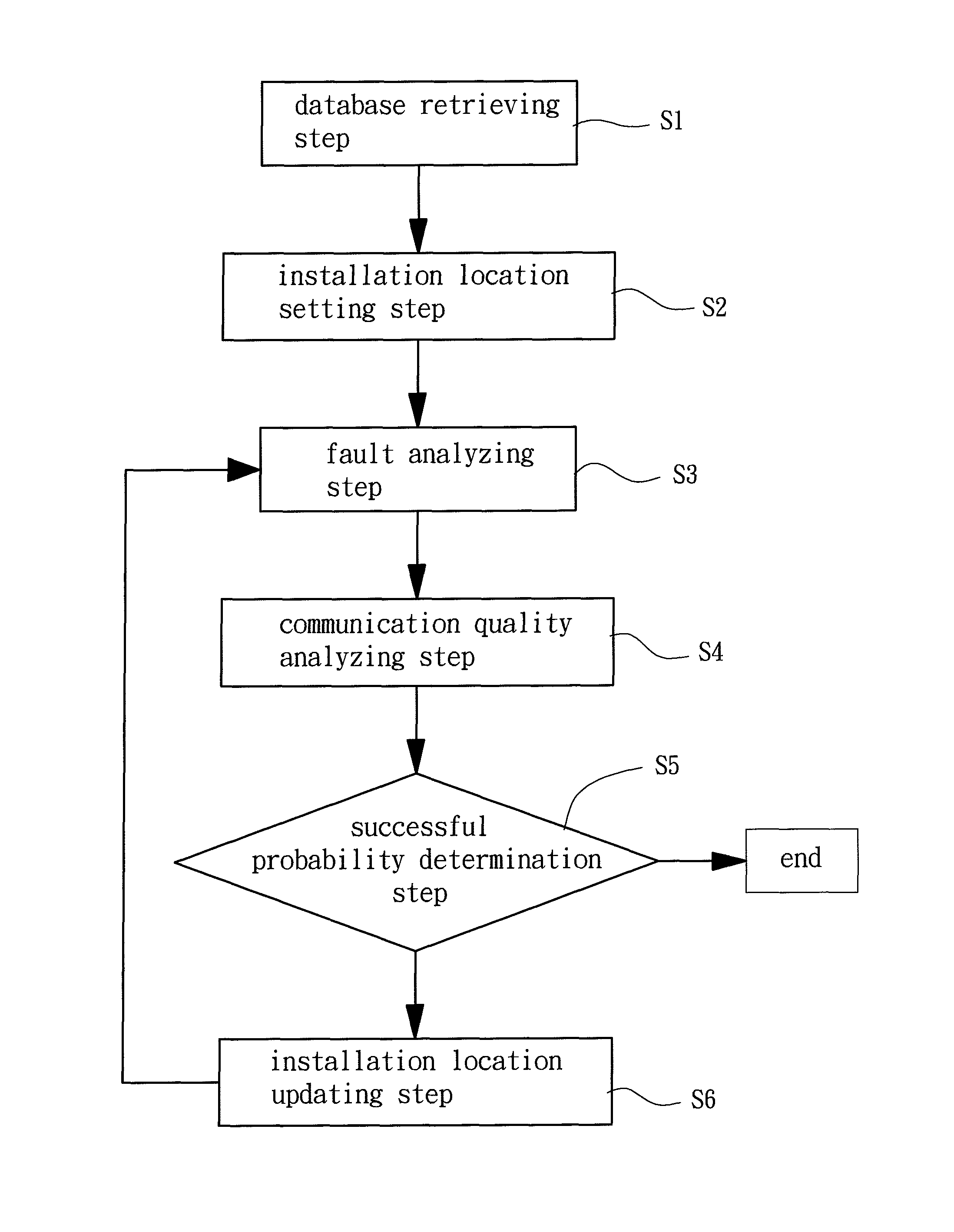
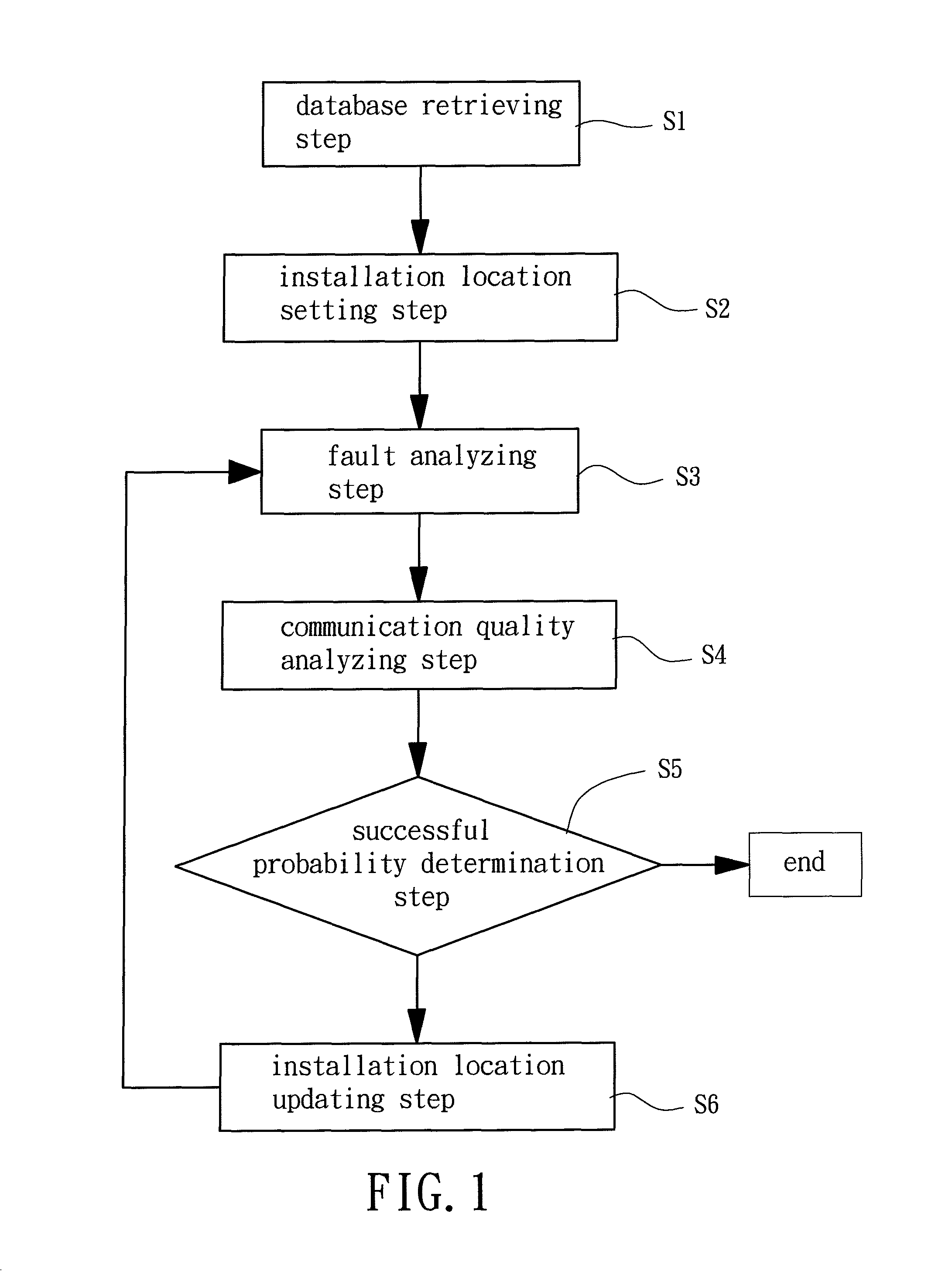
[0018]With reference to FIG. 1, a method for determining installation locations of fault indicators in a power network according to the present invention includes a database retrieving step S1, an installation location setting step S2, a fault analyzing step S3, a communication quality analyzing step S4, a successful probability determination step S5, and an installation location updating step S6.

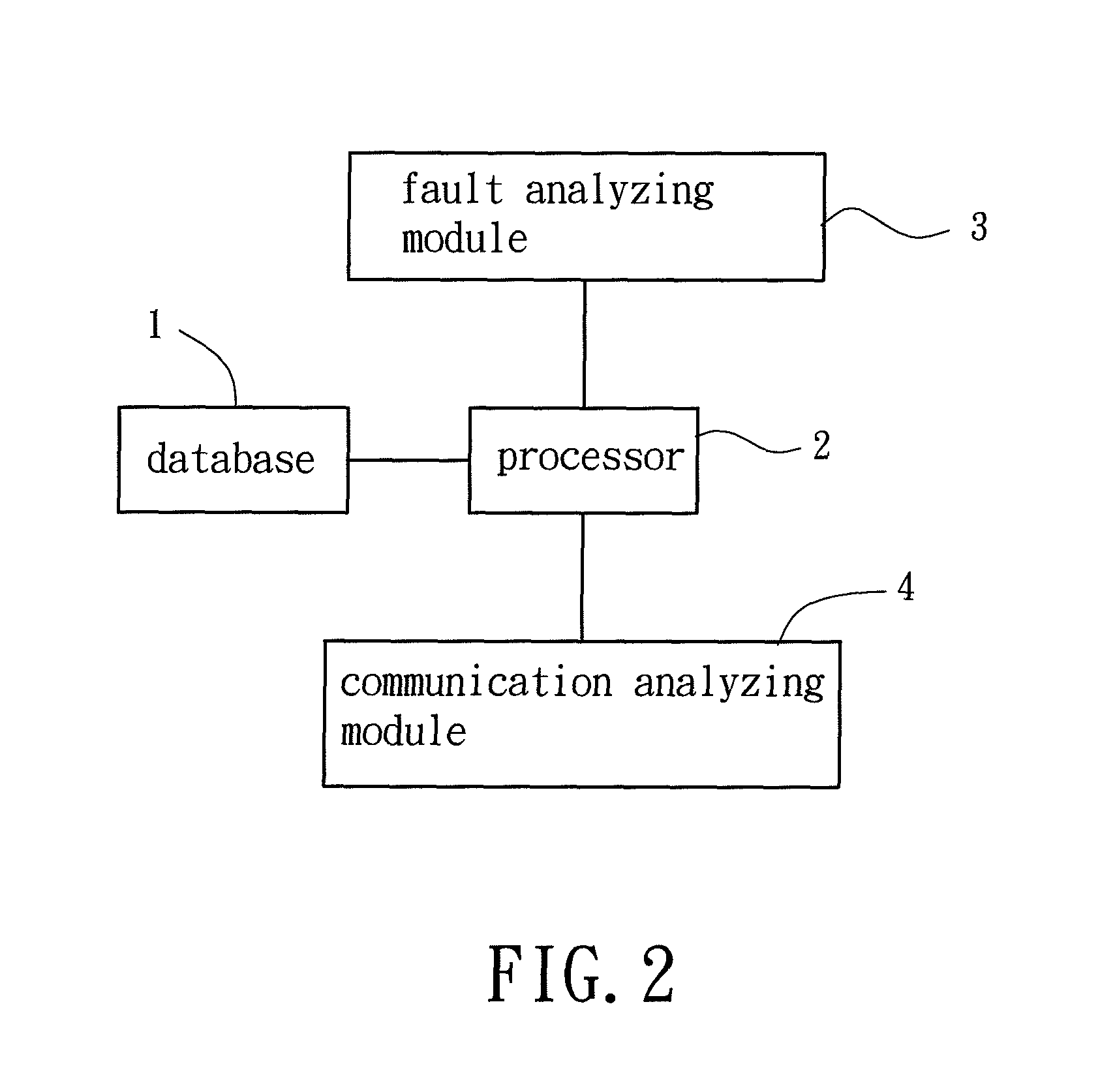
[0019]FIG. 2 shows an embodiment of an apparatus for carrying out the method for determining installation locations of fault indicators in a power network according to the present invention. The apparatus includes a database 1, a processor 2, a fault analyzing module 3 and a communication analyzing module ...


PUM


Abstract

A method for determining installation locations of a plurality of fault indicators in a power network includes a database retrieving step, an installation location setting step, a fault analyzing step, a communication quality analyzing step, a successful probability determination step and an installation location updating step. An apparatus for determining installation locations of a plurality of fault indicators in a power network includes a database, a processor, a fault analyzing module and a communication analyzing module. The processor retrieves graphical information, communication quality information, and fault rate information of feed lines of the power network from the database. The fault analyzing module generates a plurality of fault points in different zones of the power network. The communication analyzing module measures a communication quality and calculates a communication quality information cumulative probability of each zone and then calculates a successful communication probability of each zone.

Description

BACKGROUND OF THE INVENTION[0001]1. Field of the Invention[0002]The present invention relates to a method and an apparatus for determining installation locations of fault indicators and, more particularly, to a method and an apparatus for determining installation locations of fault indicators in a power network.[0003]2. Description of the Related Art[0004]A power company generally transmits power to the user ends via a power network. To smoothly transmit the power to the user ends, the power company generally installs a plurality of fault indicators at detection points of the power network to monitor the power transmission. If any nodes or feed lines in the power network malfunction and cause outage, a fault indicator near the fault location generates a fault signal and sends the fault signal to a processing center through the intermediate fault indicators between the processing center and the fault indicator sending the fault signal. The processing center judges the fault location ...

Claims


Application Information

Patent Timeline
Patent Type & Authority Patents(United States)
IPC IPC(8): G01R31/00
CPCG05B15/02G06Q10/20G06Q50/06Y04S10/54G05B23/0221Y04S10/50
Inventor CHEN, CHAO-SHUNLUAN, SHANG-WENTENG, JEN-HAO
Owner I-SHOU UNIVERSITY
Why Eureka
Try Eureka