
Self-righting frame and aeronautical vehicle

a self-righting frame and aeronautical technology, applied in the field of ovate frames, can solve problems such as initial instability, and achieve the effects of reducing structural rigidity of vertical frames, minimizing any supporting surface area, and maximum instability

Active Publication Date: 2013-09-10
ADVANCED AERODYNAMICS
View PDF13 Cites 35 Cited by
  • Summary
  • Abstract
  • Description
  • Claims
  • Application Information

AI Technical Summary

Benefits of technology

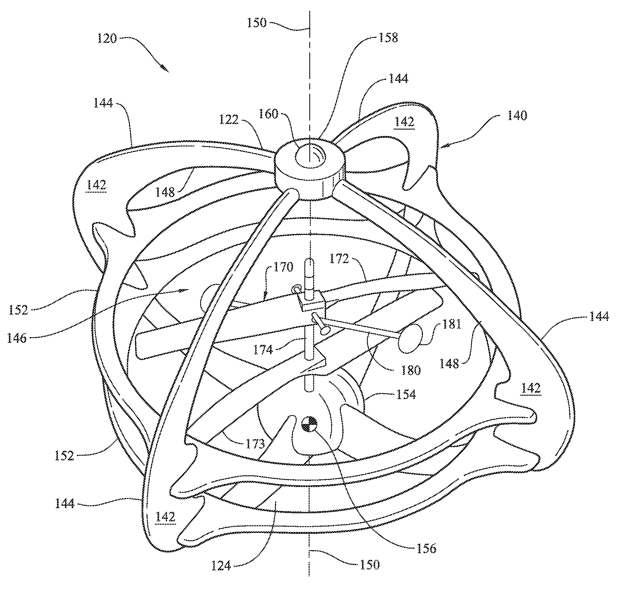
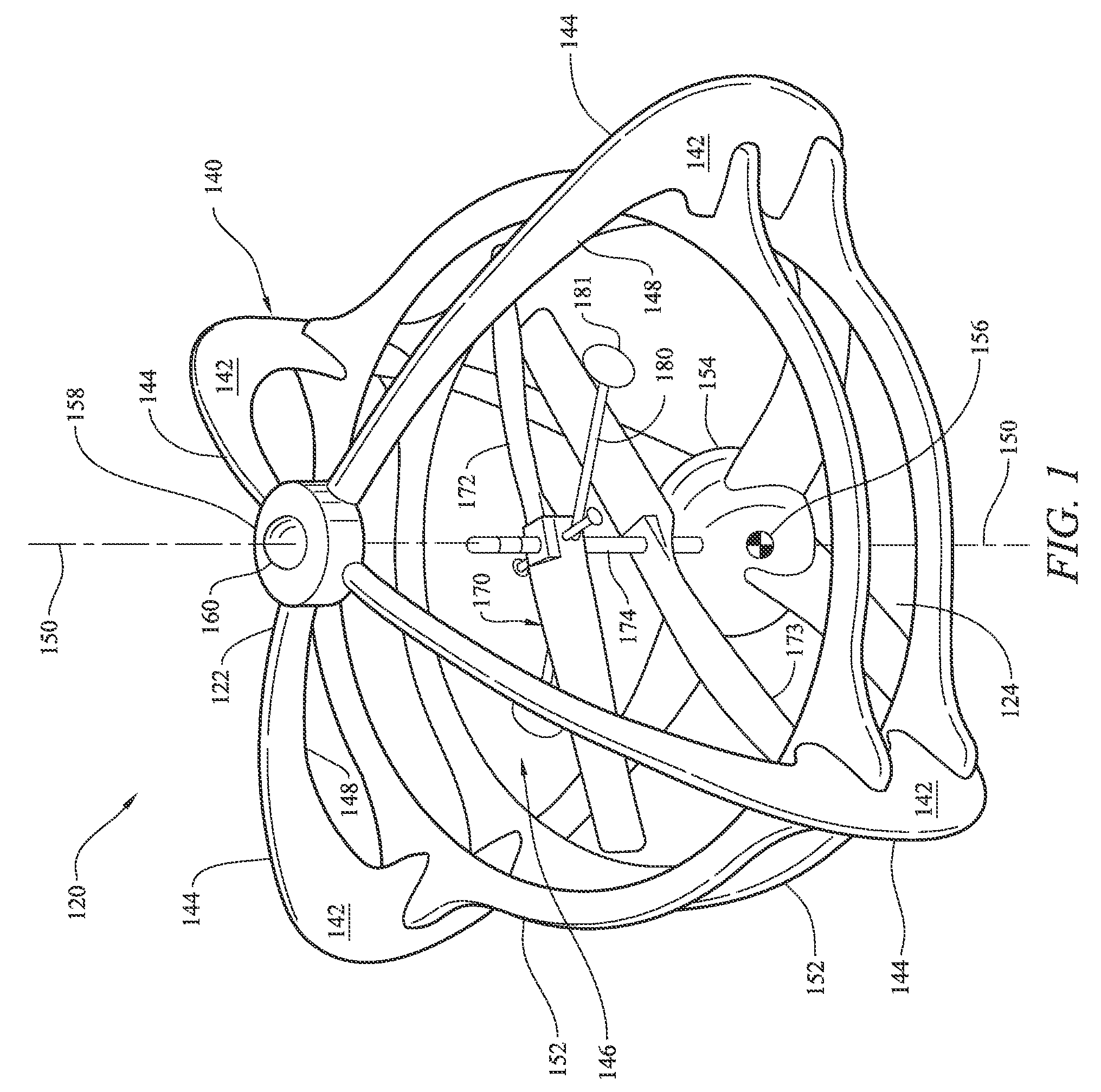
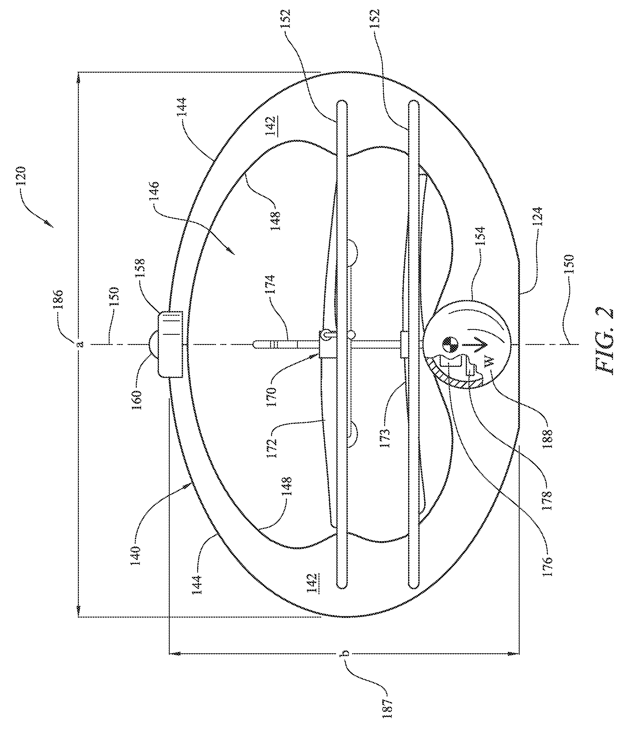
The present disclosure is about an aeronautical vehicle that can right itself from an inverted state to an upright state. The vehicle has a self-righting frame assembly that includes at least two vertical frames and at least one horizontal frame that are interconnected to maintain a fixed spatial relationship. The assembly also includes a protrusion that provides initial instability to begin the self-righting process when the vehicle is inverted. The vehicle can also have a power supply and electronics assembly for remotely controlling it. The self-righting aeronautical vehicle can be designed for manned or unmanned applications and can be of any reasonable size. The vertical and horizontal propulsion devices can be of any known by those skilled in the art. The frame can be utilized for any application desiring a self-righting structure.

Problems solved by technology

The protrusion provides an initial instability to begin a self-righting process when the aeronautical vehicle is inverted on a surface.

Method used


Image

  • Self-righting frame and aeronautical vehicle
  • Self-righting frame and aeronautical vehicle
  • Self-righting frame and aeronautical vehicle

Examples


Embodiment Construction

[0033]The following detailed description is merely exemplary in nature and is not intended to limit the described embodiments or the application and uses of the described embodiments. As used herein, the word “exemplary” or “illustrative” means “serving as an example, instance, or illustration.” Any implementation described herein as “exemplary” or “illustrative” is not necessarily to be construed as preferred or advantageous over other implementations. All of the implementations described below are exemplary implementations provided to enable persons skilled in the art to make or use the embodiments of the disclosure and are not intended to limit the scope of the disclosure, which is defined by the claims. For purposes of description herein, the terms “upper”, “lower”, “left”, “rear”, “right”, “front”, “vertical”, “horizontal”, and derivatives thereof shall relate to the invention as oriented in FIG. 1. Furthermore, there is no intention to be bound by any expressed or implied theo...


PUM


Abstract

An aeronautical vehicle that rights itself from an inverted state to an upright state has a self-righting frame assembly has a protrusion extending upwardly from a central vertical axis. The protrusion provides an initial instability to begin a self-righting process when the aeronautical vehicle is inverted on a surface. A propulsion system, such as rotor driven by a motor can be mounted in a central void of the self-righting frame assembly and oriented to provide a lifting force. A power supply is mounted in the central void of the self-righting frame assembly and operationally connected to the at least one rotor for rotatably powering the rotor. An electronics assembly is also mounted in the central void of the self-righting frame for receiving remote control commands and is communicatively interconnected to the power supply for remotely controlling the aeronautical vehicle to take off, to fly, and to land on a surface.

Description

CROSS-REFERENCE TO RELATED APPLICATION[0001]This Non-Provisional Utility application claims the benefit of co-pending Chinese Patent Application Serial No. 201010235257.7, filed on Jul. 23, 2010, which is incorporated herein in its entirety.FIELD OF THE INVENTION[0002]The present disclosure generally relates to apparatuses and methods for a frame and the construction of a frame that rights itself to a single stable orientation. More particularly, the present disclosure relates to an ovate frame that rights itself to an upright orientation regardless of the frame's initial orientation when placed on a surface.BACKGROUND OF THE INVENTION[0003]Remote controlled (RC) model airplanes have been a favorite of hobbyists for many years. Initially, in the early years of RC aircraft popularity, the radio controls were relatively expensive and required a larger model aircraft to carry the weight of a battery, receiver and the various servos to provide the remote controllability for the model ai...

Claims


Application Information

Patent Timeline
Patent Type & Authority Patents(United States)
IPC IPC(8): B64C27/08
CPCA63H27/12A63H33/005A63H30/04A63H15/06
Inventor YAN, GAOFEIDEES, JAMES
Owner ADVANCED AERODYNAMICS
Learn More