Secure logical vector clocks

a logical vector clock and clock technology, applied in the field of secure computation protocols, can solve the problems of not being the first system may not be able to gain knowledge of the processed values, and the first system may not be able to gain knowledge of the maximum value or the different values, etc., to achieve a high level of security and be easy to distribute.

Active Publication Date: 2013-09-10
SAP AG
View PDF4 Cites 4 Cited by
  • Summary
  • Abstract
  • Description
  • Claims
  • Application Information

AI Technical Summary

Benefits of technology

[0009]The first system may provide a high level of security because secure computation techniques may be used with proven security levels. The first system may be efficient because the secure computation techniques may use fast computations, have low memory requirements, and low communication overhead costs. Furthermore, the first system may be easy to implement and to update to new standards because hardware based secure computation techniques may not be required. Therefore, an exchange of central processing units or of communication units may not be required.
[0011]The second system may provide a high level of security and be efficient because secure computation techniques may be used. Furthermore, the second system may be easy to implement and update.
[0013]The third system may provide a high level of security and be efficient because secure computation techniques may be used. Furthermore, the third system may be easy to implement and update.
[0015]Accordingly, the first method, the second method, and the third method may provide a high level of security, be efficient, and be easy to implement and update.
[0017]Accordingly, the first computer program product, the second computer program product, and the third computer program product may provide a high level of security, be efficient, and be easy to distribute initially and with updates.

Problems solved by technology

With a certain level of security, the first system may not be able to gain knowledge of the maximum value or the different values.
With a certain level of security, the first system may not be able to gain knowledge of the processed values through the additional operations.
The second system may not be able to gain knowledge about the maximum value.
Furthermore, the second system may participate in additional operations of secure vector clocks without being able to gain knowledge about one or more of the processed values.

Method used


Image

  • Secure logical vector clocks
  • Secure logical vector clocks
  • Secure logical vector clocks

Examples


Embodiment Construction

[0029]The following description of examples includes details for illustrating embodiments and is not intended to limit the scope of the embodiments or to be exhaustive. For purposes of explanation, specific details are set forth in order to provide a thorough understanding of example embodiments. A person skilled in the art may appreciate that further embodiments may be practiced with details that differ from the specific details.

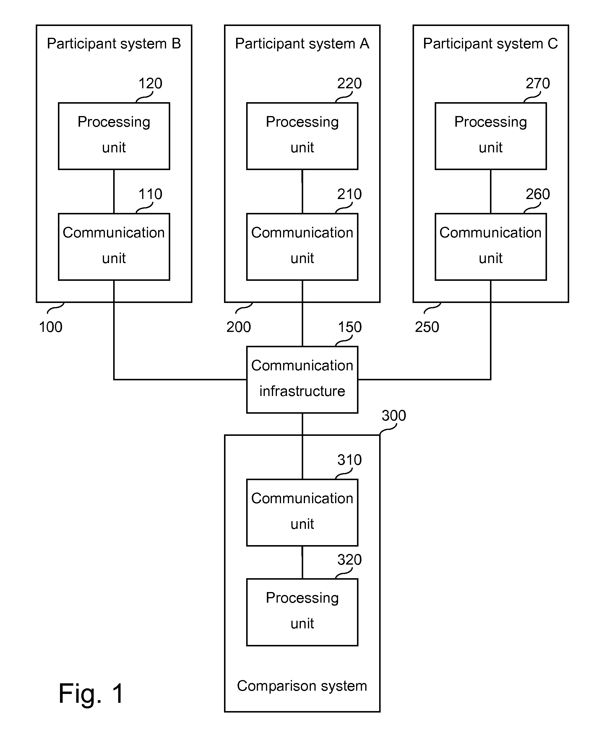
[0030]FIG. 1 is a block diagram of coupled example systems according to embodiments. The example systems include a participant system B 100 with a communication unit 110 and a processing unit 120, a participant system A 200 with a communication unit 210 and a processing unit 220, a participant system C 250 with a communication unit 260 and a processing unit 270, and a comparison system 300 with a communication unit 310 and a processing unit 320. The example systems are communicatively coupled by a communication infrastructure 150.

[0031]The participant syste...


PUM


Abstract

Embodiments include a system for processing logical clock values according to a secure maximum operation. The system may include a communication unit and a processing unit. The communication unit may be configured to receive an encrypted first value of a logical clock, send an encrypted blinded difference, receive an encrypted blinded maximum value, and receive a maximum value. The processing unit may be configured to access an encrypted second value of the logical clock, generate the encrypted blinded difference between the first value and the second value, provide an encrypted blinded first value and an encrypted blinded second value in an oblivious transfer protocol, and generate an encrypted maximum value from the encrypted blinded maximum value.

Description

CROSS-REFERENCE TO RELATED APPLICATION[0001]This application claims priority under 35 U.S.C. §119 to U.S. Provisional Patent Application No. 61 / 119,342, filed Dec. 2, 2008, titled “Secure Logical Vector Clocks,” and claims priority to EP Application 07018987.3, filed Sep. 27, 2007, both of which are incorporated herein by reference in their entirety.TECHNICAL FIELD[0002]Embodiments relate generally to the field of electronic data processing and more specifically to secure computation protocols.BACKGROUND AND PRIOR ART[0003]A distributed system may be a collection of systems that interact with each other. Each system of a distributed system may run or host a process that communicates with other processes of the distributed system. Communication may include sending and receiving messages, for example, asynchronous or synchronous messages.[0004]Logical vector clocks may be used to determine a causal relation between events of two different processes. A causal relation may be that one e...

Claims


Application Information

Patent Timeline
Patent Type & Authority Patents(United States)
IPC IPC(8): G06F11/30G06F12/14G06F21/72
CPCG06F21/72H04L9/008H04L9/30G06F2221/2107H04L2209/50H04L2209/04
Inventor KERSCHBAUM, FLORIANVAYSSIERE, JULIEN JEAN-PIERRE
Owner SAP AG
Why Eureka
Try Eureka