Aerial emergency load release mechanism

a technology of emergency release mechanism and load release mechanism, which is applied in the direction of weapons launch, transportation and packaging, agriculture tools and machines, etc., can solve the problems of halting the movement of the helicopter, damage to the helicopter, pilot injury or even death,

Active Publication Date: 2013-09-17
AERIAL SOLUTIONS
View PDF6 Cites 32 Cited by
  • Summary
  • Abstract
  • Description
  • Claims
  • Application Information

AI Technical Summary

Benefits of technology

[0017]In the event of an emergency, the pilot separately actuates each hook, e.g., by pulling on its respective actuation lever. If only one hook is released the load will stay attached to the helicopter by the other hook. The load is jettisoned only...

Problems solved by technology

One risk in transporting a load beneath a helicopter is that the load can become entangled in vegetation or other objects on the ground, halting movement of the helicopter.
Depending on the terrain, the helicopter may be prevented from landing, which can result in the helicopter crashing, causing damage to the helicopter and more importantly, injury or even death to the pilot.
Helicopter malfunctions and other emergencies may also result in a need to jettison the load from the helicopter.
One of the disadvantages of a qui...

Method used


Image

  • Aerial emergency load release mechanism
  • Aerial emergency load release mechanism
  • Aerial emergency load release mechanism

Examples


Embodiment Construction

[0021]In the following description, terms such as horizontal, upright, vertical, above, below, beneath, and the like, are used solely for the purpose of clarity in illustrating the invention, and should not be taken as words of limitation. The drawings are for the purpose of illustrating the invention and are not intended to be to scale.

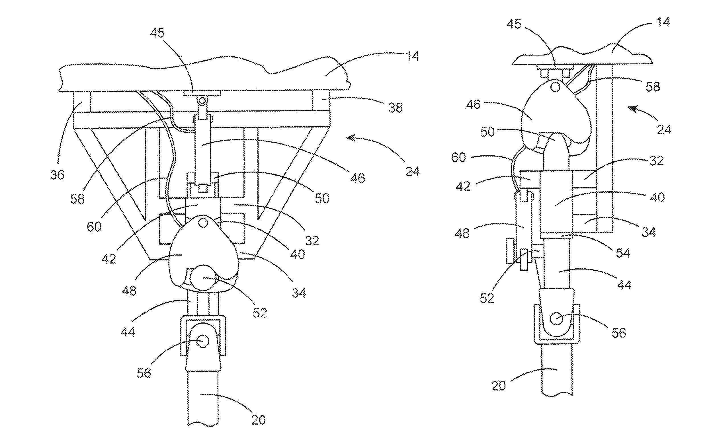
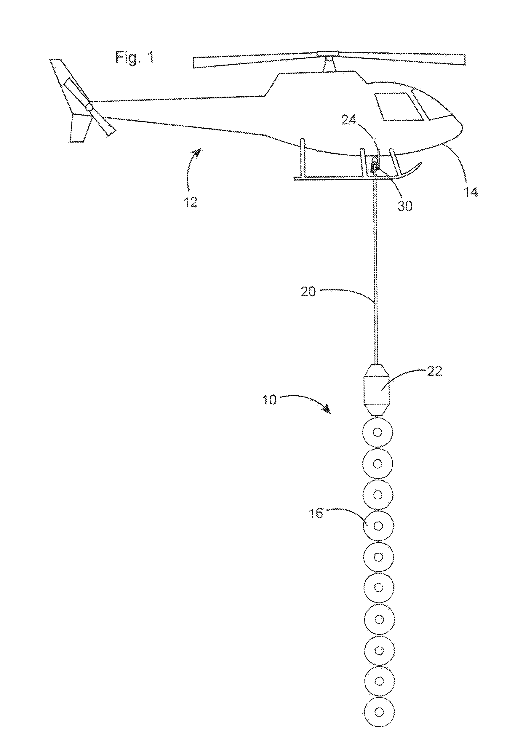
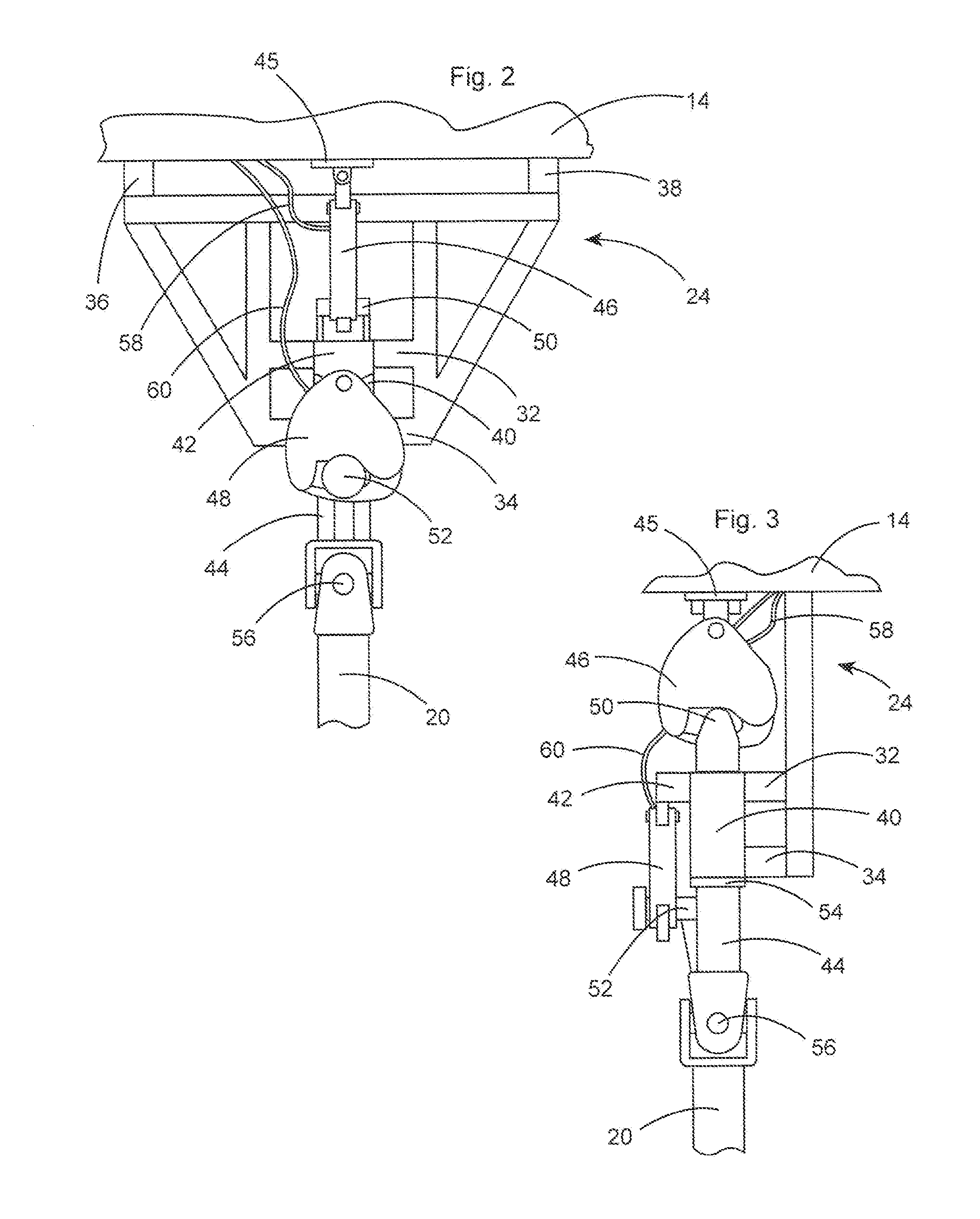
[0022]FIG. 1 illustrates a preferred embodiment of the invention for use in suspending a trimming apparatus, generally 10, beneath a helicopter, generally 12, including helicopter chassis 14. Trimming apparatus 10 is comprised of a plurality of rotatable, circular saw blades 16 aligned in a vertical plane and mounted on boom 20. Blades are rotated by engine 22. A mounting frame 24, referred to herein as a trapeze frame, is mounted on, and extends downwardly from, helicopter 12. Release mechanism 30, illustrated in detail in FIGS. 2 and 3, releasably attaches boom 20 to helicopter chassis 14 and to trapeze frame 24.

[0023]As illustrated in FIGS. 2 and ...


PUM


Abstract

An airborne tree trimming system is described that includes a helicopter having a chassis and a frame extending beneath the helicopter chassis; a trimming apparatus including a boom with an upper end and a plurality of rotatable cutting blades mounted on the boom; and a release mechanism attaching the trimming apparatus to the helicopter, the release mechanism including a connector having an upper end with a first hook attachment point, a lower end with a boom attachment point, and a second hook attachment point intermediate the upper and lower end; a first release hook mounted on the helicopter chassis and releasably attachable to the first hook attachment point; and a second release lock mounted on the frame and releasably attachable to the second hook attachment point.

Description

BACKGROUND OF THE INVENTION[0001](1) Field of the Invention[0002]The present invention relates to an emergency release mechanism for jettisoning an external load supported beneath a helicopter, and in particular to an emergency release mechanism for jettisoning a tree trimming apparatus from a helicopter if the trimming apparatus becomes entangled in trees or other material preventing movement of the helicopter.[0003](2) Description of the Prior Art[0004]It is known to trim tree limbs and other vegetation alongside power lines using an airborne system comprised of a helicopter having a trimming apparatus suspended beneath the helicopter. Systems used for this purpose are described, for example, in U.S. Pat. Nos. 4,815,263 and 4,984,757. Helicopters are also used to carry other external loads such as cargo, water containers, vehicles, etc., suspended on an attachment member, such as a cable, extending downwardly beneath the helicopter. As used herein, the term “load” is used to gener...

Claims


Application Information

Patent Timeline
IPC IPC(8): B64D1/00A01G3/08B64D1/12A01G3/00A01G3/04
CPCA01G23/095B64D1/22B64C27/04
Inventor COX, IV, WILLIAM CLEVELAND
Owner AERIAL SOLUTIONS
Why Eureka
Try Eureka