
Ladder hanging assembly and method

a technology of ladders and brackets, applied in the field of ladders, can solve the problems of limiting use, cumbersome use, and difficult storage, and achieve the effects of less effort, easy storage, and convenient turning

Active Publication Date: 2013-09-17
ANDERSON PAUL W
View PDF6 Cites 5 Cited by
  • Summary
  • Abstract
  • Description
  • Claims
  • Application Information

AI Technical Summary

Benefits of technology

The ladder hanger assembly of this patent allows for easier storage and retrieval of ladders, as they can be positioned and pivoted between a stowed position and a released position. The assembly includes a lifting mechanism that can raise or lower the ladder, and a second ladder hanger that can be rotated or pivoted to secure the ladder in a storage space. The ladder is stored in a way that preserves more usable space, and the assembly is designed to be easily operated by users without the need for a step stool. These technical effects make the ladder hanger assembly more convenient and efficient for users.

Problems solved by technology

One difficulty with ladders is that they are often hard to store when not in use.
Some ladders may be taller than the interior dimensions of a room requiring that the ladders be stored on the floor where they are often in the way or can be damaged.
Various different systems have been developed for storing ladders on side walls or adjacent ceilings but, often, these systems are cumbersome to use which ultimately limits their use.
While these hooks are capable of storing a ladder adjacent a wall or ceiling, these hooks are often difficult for the average person to use.
This problem is particularly apparent with hooks that are to be positioned adjacent ceilings.
Because, the typical ceiling is higher than an average person can reach, to hang ladders from the hooks, the person is obligated to use a step stool or other device to hang the ladder which complicates the use of the hooks.
Various other hanging assemblies have been disclosed, yet each of these systems typically require the use of step stools or require significant user manipulation of the hanging assembly to store the ladders.
This results in the ladder occupying an increased amount of space which can be problematic with crowded storage spaces.
As such, existing ladder storage systems and methods are often not popular due to their bulky and cumbersome nature.

Method used


Image

  • Ladder hanging assembly and method
  • Ladder hanging assembly and method
  • Ladder hanging assembly and method

Examples


Embodiment Construction

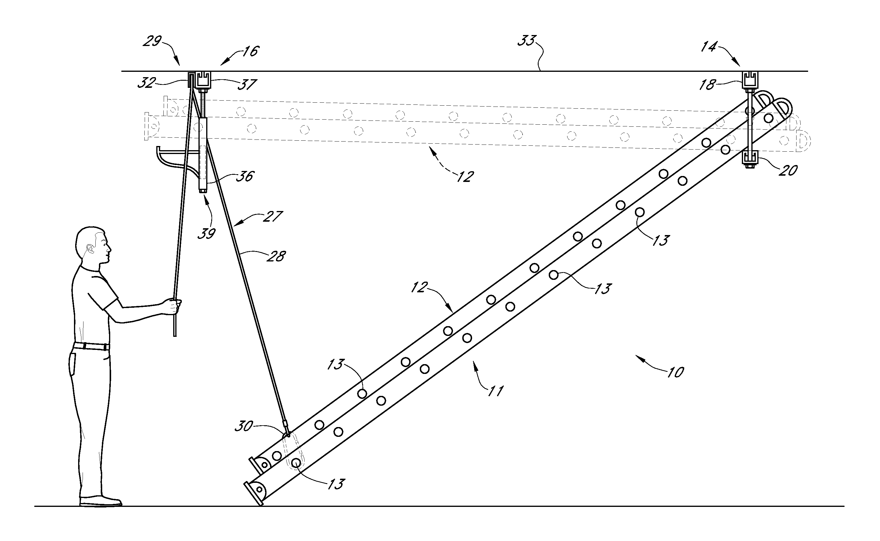
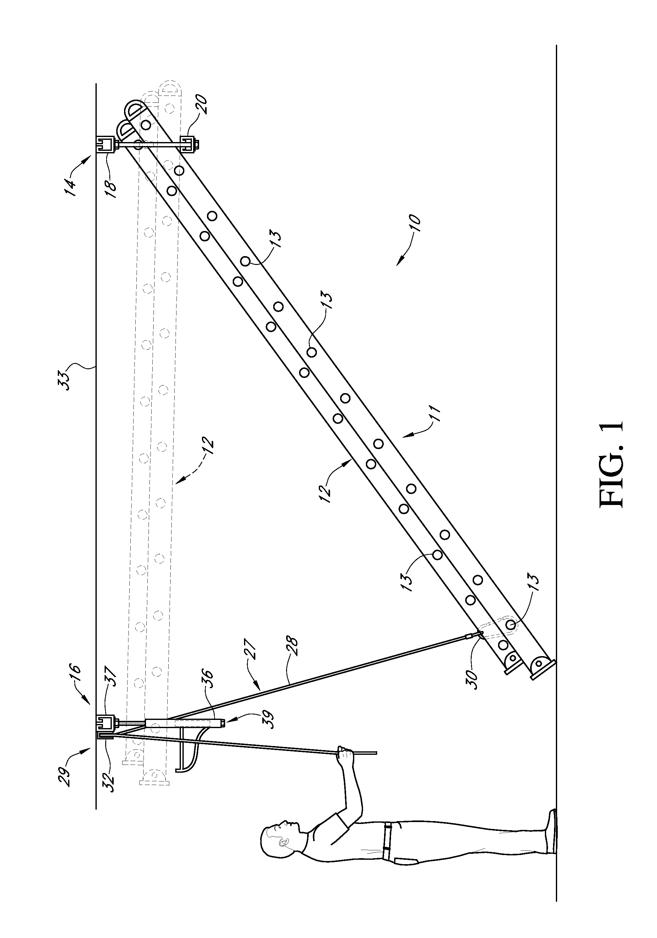
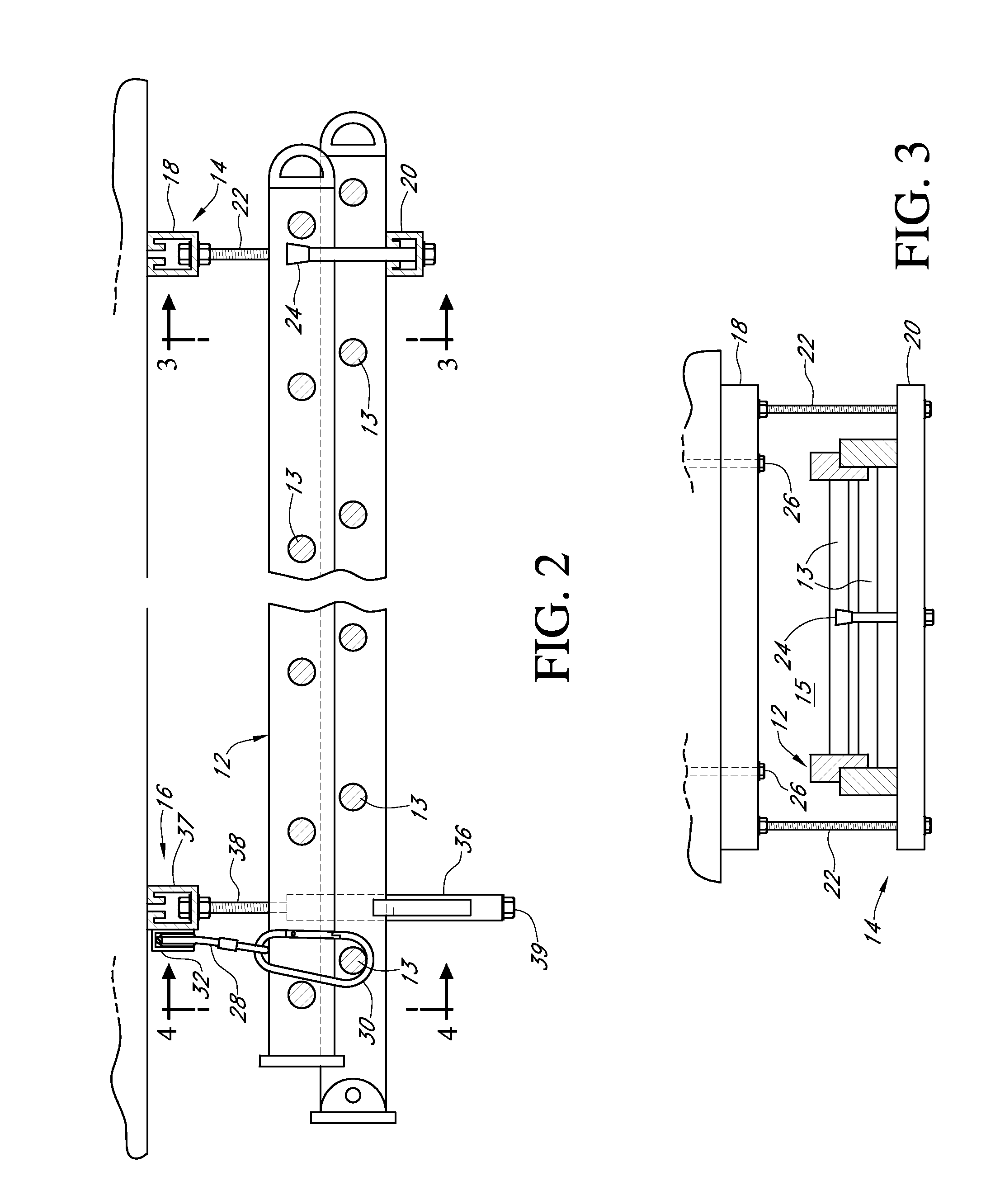
[0032]Reference will now be made to the drawings wherein like numerals refer to like parts throughout. Referring initially to FIGS. 1-5, a first embodiment of a ladder hanging assembly 10 and method of use thereof is illustrated. As shown in FIG. 1, the assembly 10 includes a first ladder hanger 14 that is mounted to the ceiling. The first ladder hanger 14 defines an aperture 15 (FIG. 3) that is sized so as to receive a ladder 11. The first ladder hanger 14 is generally fixed in that it defines an aperture that receives a first end of the ladder. As will be discussed in greater detail below, however, the first ladder hanger 14 is formed so as to be flexible to accommodate swaying motion, etc.

[0033]As is also shown in FIGS. 1 and 2, the assembly 10 also includes a second ladder hanger 16 that is generally movable between a open configuration and a closed configuration. In the open configuration, the second ladder hanger 16 allows for ladders to be positioned within or removed from a ...


PUM


Abstract

An assembly for hanging ladders from surfaces such as ceilings and walls. The assembly includes a first ladder hanger that defines an aperture that receives a first end of the ladder and a second ladder hanger that receives a second end of the ladder. The second ladder hanger includes movable members that can be moved to permit the second end of the ladder to be stored in the storage space and can further retain the ladder in the storage space. In one implementation, rotating members are used to manipulate the ladder hanger into a storage configuration, in another implementation; pivoting members are used.

Description

CROSS-REFERENCE TO RELATED APPLICATIONS[0001]This application claims the benefit of U.S. Provisional Application No. 61 / 109,255 filed on Oct. 29, 2008 entitled Tall Ladder Storage System and in the Applicant's name of Paul W. Anderson, which is hereby incorporated in its entirety by reference herein.BACKGROUND OF THE INVENTION[0002]1. Field of the Invention[0003]The present invention relates to ladders and, in particular, concerns systems and methods for storing ladders adjacent the ceilings of rooms.[0004]2. Description of the Related Art[0005]Ladders come in all different shapes and sizes. Many home owners end up owning several ladders for use around the house. These can include step ladders, extension ladders and the like. Some business owners have multiple ladders of multiple different sizes. For example, painters and other construction workers may own multiple different ladders of different sizes for multiple different applications.[0006]One difficulty with ladders is that they...

Claims


Application Information

Patent Timeline
Patent Type & Authority Patents(United States)
IPC IPC(8): F16M11/00
CPCE06C1/12E06C7/06E06C7/505
Inventor ANDERSON, PAUL W.
Owner ANDERSON PAUL W
Learn More