Spindle motor and hard disk drive including the same

a spindle motor and hard disk drive technology, applied in the direction of sliding contact bearings, instruments, record information storage, etc., can solve the problems of reducing the rotational characteristics of the spindle motor and reducing the clearan

Inactive Publication Date: 2014-06-12
SAMSUNG ELECTRO MECHANICS CO LTD
View PDF0 Cites 0 Cited by
  • Summary
  • Abstract
  • Description
  • Claims
  • Application Information

AI Technical Summary

Benefits of technology

[0010]An aspect of the present invention provides a spindle motor in which an introduction of an external foreign object and l

Problems solved by technology

In a case in which a lubricating fluid is released from a liquid-vapor interface formed by the lubricating fluid and air and leaked outwardly, rotational characteris

Method used


Image

  • Spindle motor and hard disk drive including the same
  • Spindle motor and hard disk drive including the same
  • Spindle motor and hard disk drive including the same

Examples


first embodiment

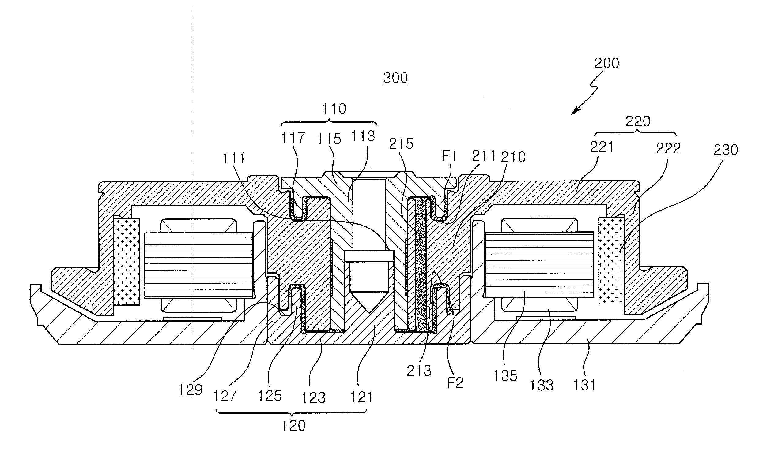
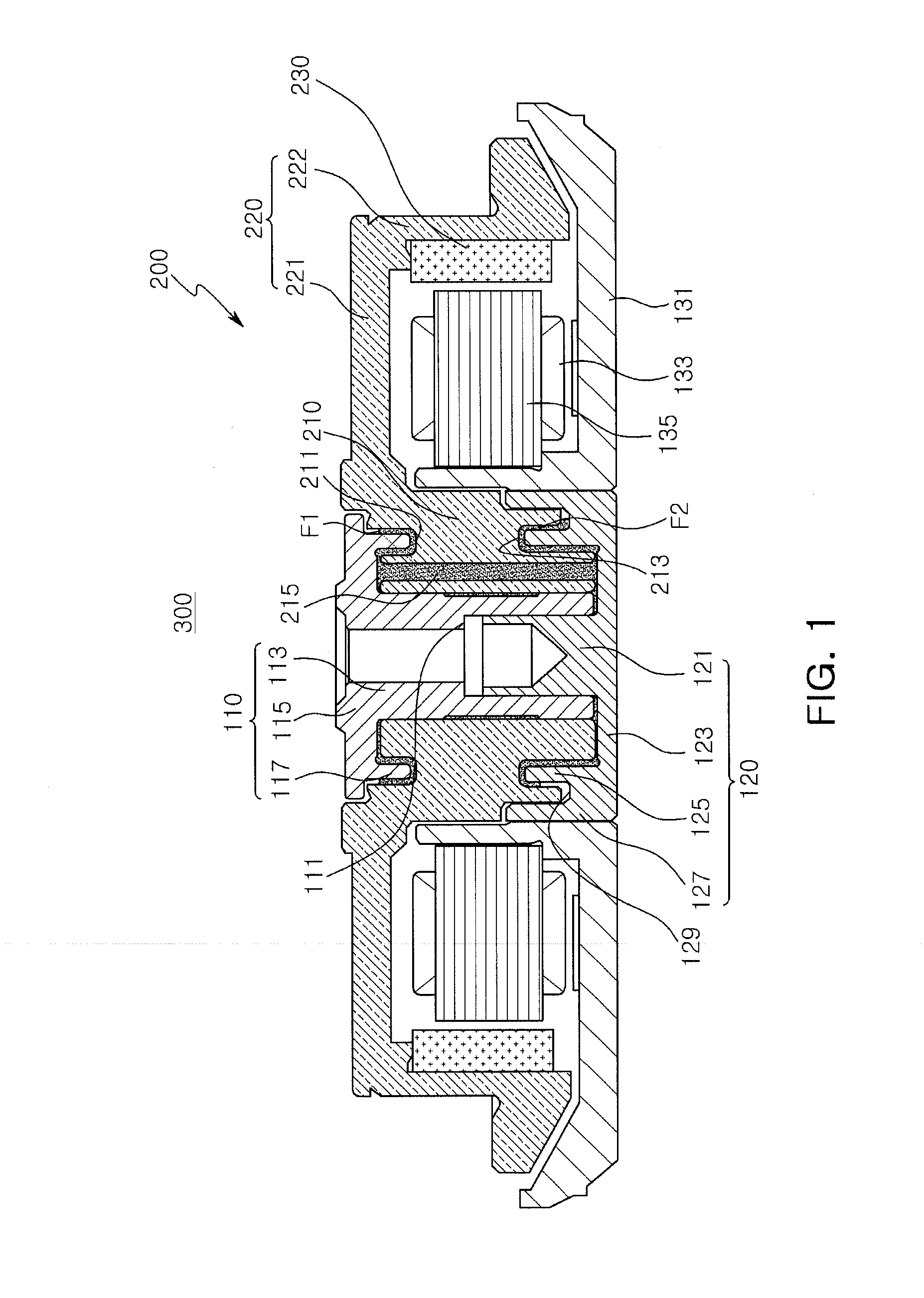
[0060]FIG. 1 is a schematic cross-sectional view of a spindle motor according to the present invention.

[0061]Referring to FIG. 1, a spindle motor according to a first embodiment of the present invention may include a fixed member including the shaft 110, a lower thrust member 120, and a base member 131, and a rotating member 200.

[0062]The shaft 110 and the lower thrust member 120 may constitute a fixed member together with the base member 131.

[0063]The shaft 110 may be installed to be indirectly fixed to the base member 131 by the medium of the lower thrust member 120, and may constitute a fixed member together with the lower thrust member 120 and the base member 131.

[0064]The shaft 110 may include a body portion 113 inserted into a shaft hole of the rotating member 200, a flange portion 115 extending in the outer radial direction from an upper portion of the body portion 113, and a first insertion portion 117 extending downwardly from the flange portion 115 in an axial direction.

[0...

second embodiment

[0133]FIG. 7 is a schematic cross-sectional view of a spindle motor according to the present invention.

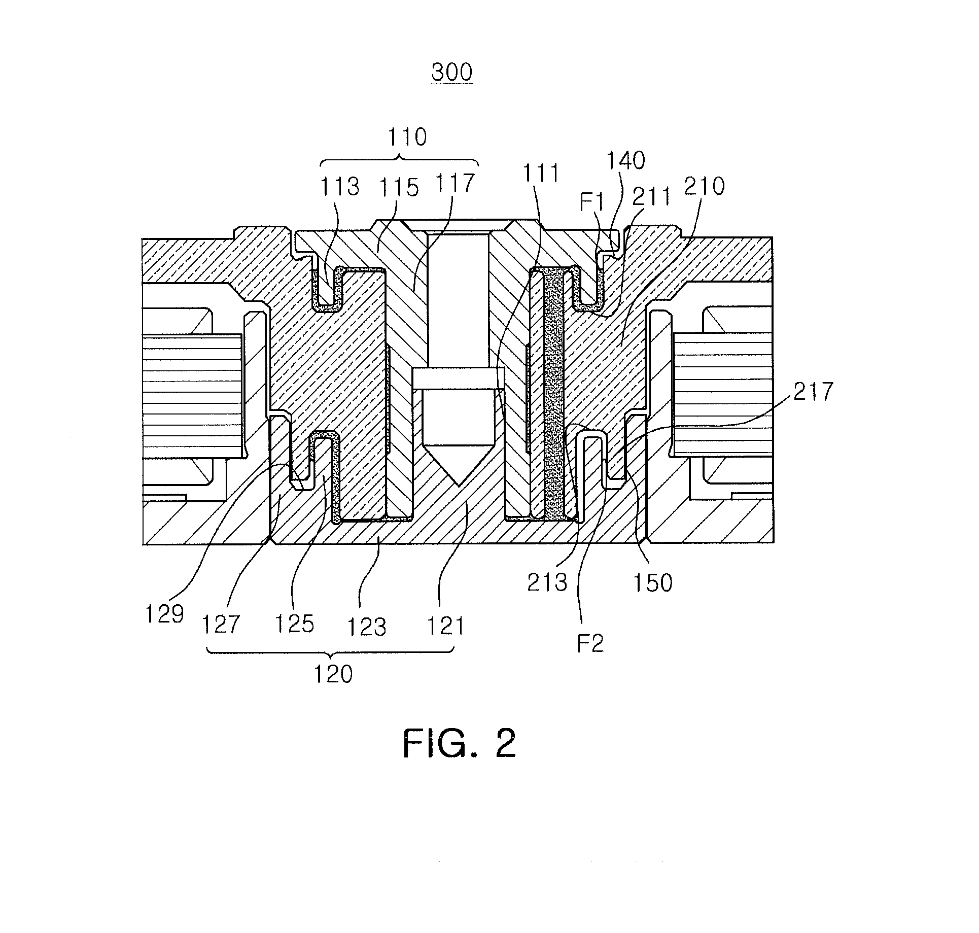
[0134]Referring to FIG. 7, a spindle motor 400 according to the second embodiment of the present invention may have the same configuration as that of the spindle motor 300 according to the first embodiment of the present invention, except for the labyrinth sealing portions 140, 150, and 160, so description of components other than the labyrinth sealing portions 140, 150, and 160 will be omitted.

[0135]The upper labyrinth sealing portion 140 may be formed between the flange portion 115 provided in the shaft 110 and the rotating member 200.

[0136]In detail, a micro-clearance may be formed between an outer edge of the flange portion 115 and a surface of the rotating member 200 facing the outer edge of the flange portion 115 to form the upper labyrinth sealing portion 140.

[0137]Here, a recess 115a may be formed on at least one of a lower surface and a lateral surface of the outer edge of...

fourth embodiment

[0155]FIG. 10 is a schematic cross-sectional view of a spindle motor according to the present invention.

[0156]Referring to FIG. 10, a spindle motor 600 according to the fourth embodiment of the present invention has the same configuration as that of the spindle motor 300 according to the first embodiment of the present invention, except for the shaft 110 and a cover member 170, so a description of components other than the shaft 110 and the cover member 170 will be omitted.

[0157]An upper surface of the rotating member 200 may have a step in order to fix the cover member 170 therein.

[0158]The cover member 170 may be fixedly disposed in the step portion of the upper surface of the rotating member 200, restraining leakage and evaporation of a lubricating fluid.

[0159]An upper surface of the flange portion 115 may face a lower surface of the cover member 170 and a micro-clearance may be formed between the upper surface of the flange portion 115 and the cover member 170 to constitute the ...


PUM


Abstract

There is provided a spindle motor including: a shaft including a body portion having a fixing recess formed on a lower portion thereof, a flange portion extending in an outer radial direction from an upper portion of the body portion, and a first insertion portion extending downwardly from the flange portion in an axial direction; a lower thrust member including a fixed portion inserted into the fixing recess, a disk portion extending from the fixed portion in an outer radial direction, and first and second protrusion portions extending from the disk portion in the axial direction; a base member coupled to the second protrusion portion; and a rotating member forming a bearing clearance with the shaft and provided to be rotatable with respect to the shaft.

Description

CROSS-REFERENCE TO RELATED APPLICATIONS[0001]This application claims the priority of Korean Patent Application No. 10-2012-0143968 filed on Dec. 11, 2012, in the Korean Intellectual Property Office, the disclosure of which is incorporated herein by reference.BACKGROUND OF THE INVENTION[0002]1. Field of the Invention[0003]The present invention relates to a spindle motor and a hard disk drive including the same.[0004]2. Description of the Related Art[0005]A so-called shaft fixed type spindle motor may be mounted in an information recording and reproducing apparatus such as a hard disk drive, or the like, in which a shaft resistant to vibration is fixed to a case of a hard disk drive.[0006]Namely, in order to prevent recorded information from being damaged and a state in which information cannot be written or read due to external vibrations developing, a spindle motor installed in a hard disk drive may employ a structure in which a shaft is fixedly installed.[0007]Meanwhile, a spindle ...

Claims


Application Information

Patent Timeline
IPC IPC(8): H02K7/08G11B19/20
CPCG11B19/2009H02K7/086F16C17/10F16C33/10G11B19/20H02K5/173
Inventor SMIRNOV, VIATCHESLAV
Owner SAMSUNG ELECTRO MECHANICS CO LTD
Why Eureka
Try Eureka