
electric vehicle

A technology for electric vehicles and electric motors, which is applied in electric vehicles, electric scooters, motor vehicles, etc., can solve the problems of longer wheelbases of front and rear wheels, larger body size, etc., and achieve the effect of ensuring battery capacity

Active Publication Date: 2016-12-28
HONDA MOTOR CO LTD
View PDF4 Cites 0 Cited by
  • Summary
  • Abstract
  • Description
  • Claims
  • Application Information

AI Technical Summary

Problems solved by technology

However, in this method, the wheelbase, which is the distance between the front and rear wheels, becomes longer, resulting in a larger vehicle body

Method used


Image

  • electric vehicle
  • electric vehicle
  • electric vehicle

Examples


no. 1 approach

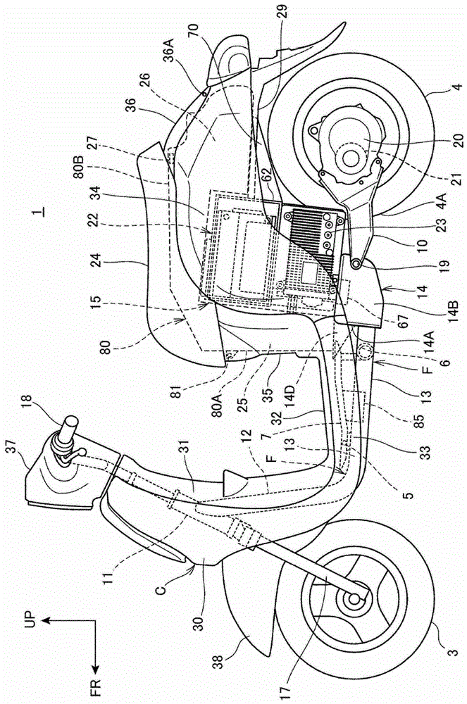
[0094] figure 1 It is a left side view of the electric vehicle according to the first embodiment of the present invention.

[0095] Such as figure 1 As shown, the electric vehicle 1 is a scooter-type electric two-wheeled vehicle with a low floor 32 for the driver to put his feet on, and has a front wheel 3 in front of the vehicle frame F, and a rear wheel 4 (wheel) as a driving wheel is formed by The frame F is supported by a swing arm 10 connected to the rear. The frame F is covered with a body cover C made of resin.

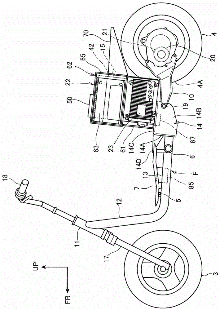
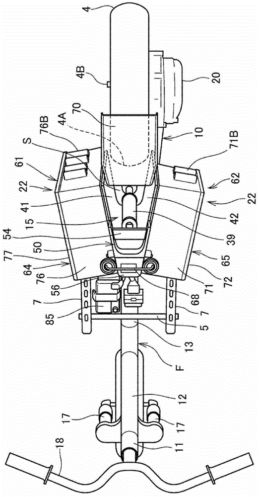
[0096] figure 2 It is a left side view of the electric vehicle 1 with the body cover C removed. image 3 It is a figure which looked at the electric vehicle 1 in the state which removed the vehicle body cover C from above. Figure 4 It is a plan view of the electrically powered vehicle 1 in a state where the body cover C is removed, viewed from below. Figure 5 It is a perspective view of the electric vehicle 1 in a state where the body cover C is remove...

no. 2 approach

[0176] Below, refer to Figure 12 , and the second embodiment to which the present invention is applied will be described. In this second embodiment, the same reference numerals are assigned to the same components as those in the above-mentioned first embodiment, and description thereof will be omitted.

[0177] In the above-mentioned first embodiment, the structure in which the blower fan 67 is arranged under the plates 42, 41 has been described, but this second embodiment differs from the above-mentioned first embodiment in that the plates 42, 41 A blower fan 267 (fan) is arranged on the top of 41 .

[0178] Figure 12 It is a left side view of the electric vehicle 1 with the body cover C and the storage box 80 removed in the second embodiment.

[0179] Such as Figure 12 As shown, the hollow portion 44 ( Figure 6 ) The air blowing fan 267 sucked out to face the opening 55 of the bracket 50 ( Figure 7 ) mode is installed on the upper surface of the bracket 50. A duc...


PUM


Abstract

The present invention provides an electric vehicle capable of securing a wide battery space without increasing the wheelbase. The electric vehicle is equipped with a battery (22), and the electric vehicle drives a motor (21) for driving the vehicle with electric power of the battery (22), wherein the electric vehicle is provided with a battery supporting the battery (22). A frame (15), the battery frame (15) has a pair of left and right plates (42, 41) on the left and right of the rear wheel (4) of the electric vehicle (1), and the battery (22) is distributed to each plate (42, 41) and supported by the plates (42, 41).

Description

technical field [0001] The present invention relates to an electric vehicle in which a vehicle-driving motor is driven by electric power from a battery. Background technique [0002] Conventionally, an electric vehicle including a battery frame supporting a battery is known as an electric vehicle (for example, refer to Patent Document 1). In Patent Document 1, a pair of left and right sheet metal support cases functioning as a battery frame are arranged above the rear wheel and below the seat, and the battery is supported on the support cases. According to this configuration, since a rigid battery frame is used, a relatively heavy battery can be supported with sufficient supporting strength. [0003] [Patent Document 1] Japanese Patent Application Laid-Open No. 4-358983 [0004] However, in the conventional electric vehicle described above, since the battery frame is disposed above and in front of the rear wheels, the position of the battery is limited to a position higher...

Claims


Application Information

Patent Timeline
Patent Type & Authority Patents(China)
IPC IPC(8): B62K11/10B60K1/04B62M7/12
CPCB60K1/04B60K7/0007B60K11/06B60K2001/005B60K2001/0422B60K2007/0038B60K2007/0092B60L2200/12B60Y2200/126B62K11/10B62K2202/00B62K2204/00B62M7/12B60L50/66B62J43/16B62J43/20Y02T10/70
Inventor 堀井义之
Owner HONDA MOTOR CO LTD
Learn More