Clubhead with external hosel

a clubhead and hosel technology, applied in the field of golf clubs, can solve the problems of increasing vibration, loss of stability, and loss of benefits derived from increasing the moment of inertia, and achieve the effect of improving performan

Active Publication Date: 2013-09-17
EHT GOLF DESIGN +1
View PDF28 Cites 25 Cited by
  • Summary
  • Abstract
  • Description
  • Claims
  • Application Information

AI Technical Summary

Benefits of technology

[0007]In the present invention the flanged hosel, and thus the club shaft, positioned in an external location from the club head. The flanged hosel may be placed at any location on the periphery of the skirt. A range of shaft position options (relative to the plane of the club face) are possible by the permanent positioning of the flanged hosel at various positions on the skirt of the club head. The flanged hosel does not at any point intersect with the crown, sole or face of the club head. This design allows the club head to maintain a consistent shape, allows for an offering of shaft positions that are pleasing to the eye and deliver the club head to impact position based on the individual player type's needs, and thus performance will be improved.

Problems solved by technology

However, any benefits derived from increasing the moment of inertia are lost due to an increase in vibration and loss of stability.

Method used


Image

  • Clubhead with external hosel
  • Clubhead with external hosel
  • Clubhead with external hosel

Examples


Embodiment Construction

[0018]The detailed embodiments of the present invention are disclosed herein. It should be understood, however, that the disclosed embodiments are merely exemplary of the invention, which may be embodied in various forms. Therefore, the details disclosed herein are not to be interpreted as limiting, but as a basis for the claims and for teaching one skilled in the art how to make and / or use the invention.

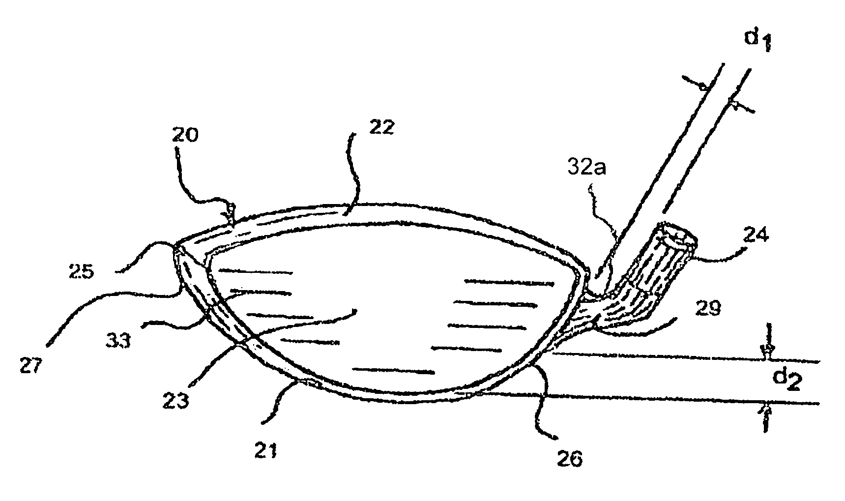
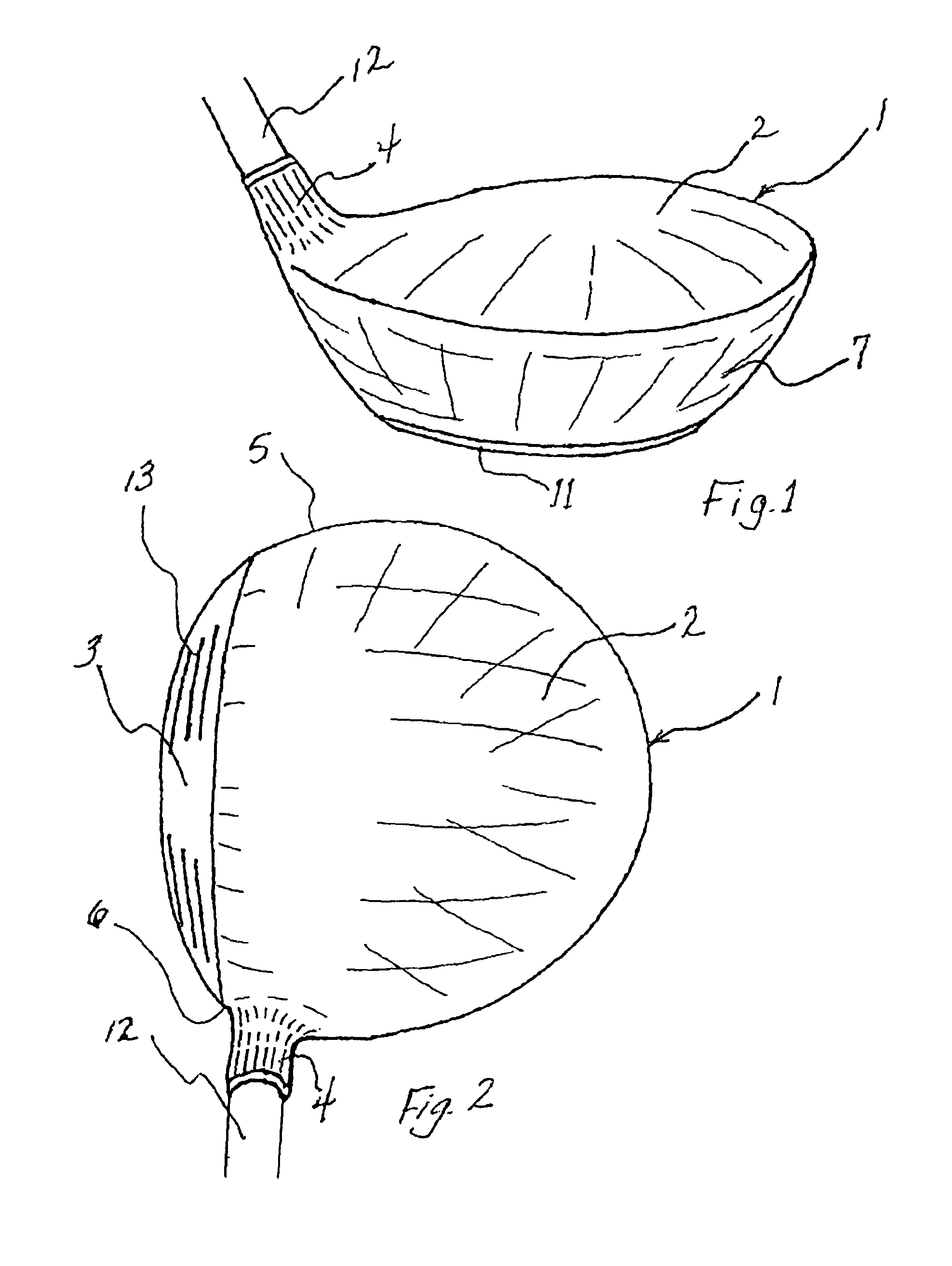
[0019]With reference to FIGS. 1 and 2, a prior art golf club head is shown. The golf club head 1 includes a face 3, a soleplate 11, a crown 2, a toe 5, a heel 6, a skirt 7, or other structure, used in connecting the crown 2 to the soleplate 11, and a hosel 4 to which a golf club shaft 12 is secured, as well as any weight member(s) which might be incorporated into the club head 1. As is readily apparent, the hosel is within the periphery of club head 1, and flows directly from crown 2.

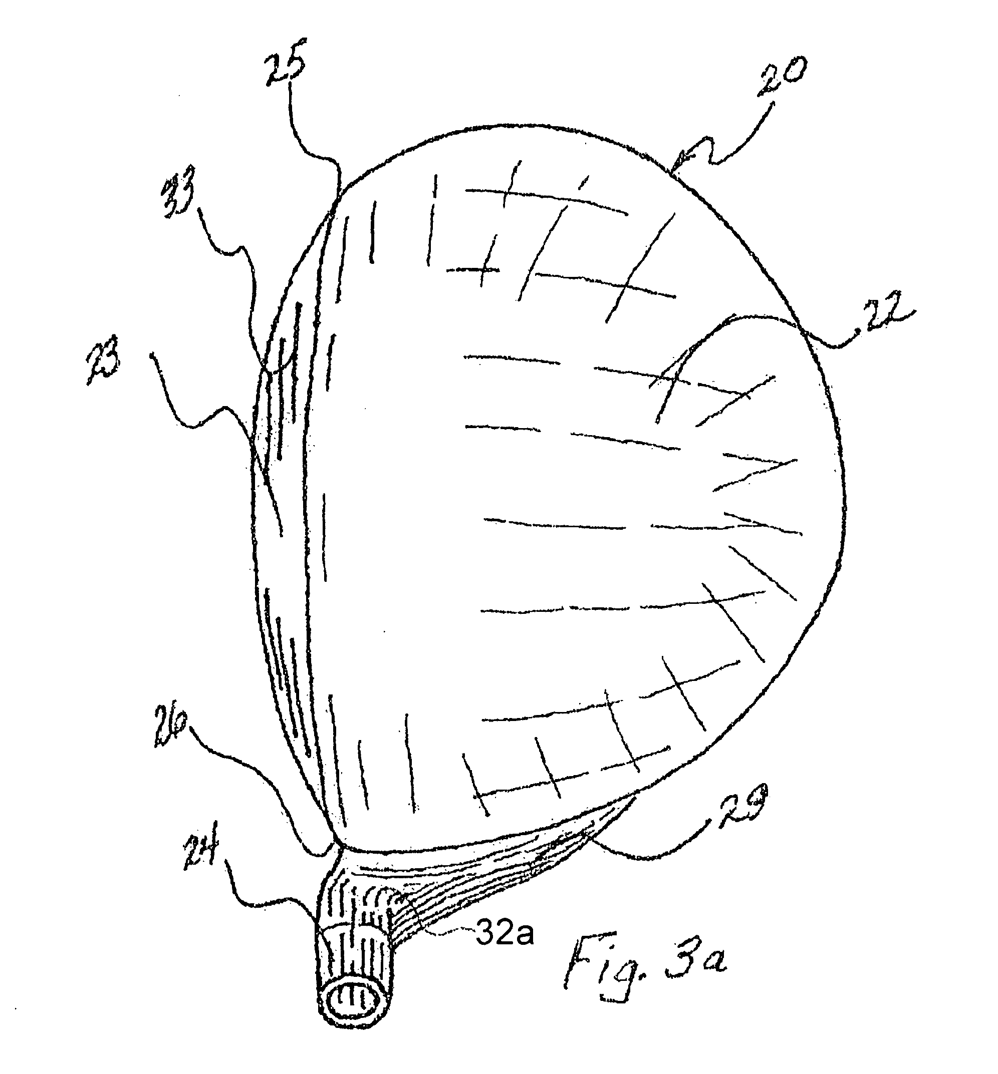
[0020]Although a driver type golf club head, frequently called a “wood,” is disclosed herein in acco...


PUM


Abstract

A golf club head consisting of a striking face, a soleplate, a crown, and a skirt connecting the face, the soleplate and the crown. A flange is placed at a selected location on the periphery of the skirt. Incorporated into the flange is a hosel, positioned to be displaced from the club head, for receiving the shaft of the golf club. The area of the skirt covered by the flange has a length versus height ratio.

Description

[0001]This application is based on and takes priority from U.S. Provisional Patent Application Ser. No. 61 / 210,014 entitled “Club Head With External Flange,” filed on Mar. 13, 2009.FIELD OF THE INVENTION[0002]This invention pertains to golf apparatus, and more particularly to golf clubs, and more particularly to golf woods, fairway metal club and hybrid style clubs.BACKGROUND OF THE INVENTION[0003]Golf club makers may use slightly different manufacturing processes. Some parts of the manufacturing process may be unique to one company and regarded as trade secrets. Regardless of the type of process, woods, which may be drivers, fairway woods, and hybrid style clubs, generically “woods,” are typically designed the same. Throughout this application, “club head” and “wood head” may be used interchangeably. The head is comprised of a sole (bottom), skirt (about the periphery), a crown (top) and a face (the hitting surface). Formed in the crown and adjacent, and attached to, the skirt is a...

Claims


Application Information

Patent Timeline
Patent Type & Authority Patents(United States)
IPC IPC(8): A63B53/02A63B53/04
CPCA63B53/02A63B53/0466A63B59/0092A63B2053/0433A63B2053/0491A63B2225/01A63B2053/021A63B60/54A63B53/021A63B53/0433A63B60/02
Inventor MCGINNIS, JR., THOMAS WILLIAM
Owner EHT GOLF DESIGN
Why Eureka
Try Eureka