Travel damper control device for wheel loader

a technology for dampers and loaders, applied in the direction of fluid couplings, instruments, couplings, etc., can solve the problems of degrading durability of accumulators, earth and sand load, and load on work implements attached to the tips of pair of booms, so as to inhibit the degradation of accumulators durability

Active Publication Date: 2013-09-17
KOMATSU LTD
View PDF24 Cites 3 Cited by
  • Summary
  • Abstract
  • Description
  • Claims
  • Application Information

AI Technical Summary

Benefits of technology

[0009]According to the travel damper control device for a wheel loader of the first aspect of the present invention, the open / close valve is configured to be switched into the closed position at a point of time when it is detected that the bell crank is in proximity to the cross tube. In other words, it is possible to quickly block communication between the boom cylinder and the accumulator before the cross tube is hit with the bell crank. It is thereby possible to inhibit an acute peak pressure, generated in the boom cylinder in executing a rap-out, from being transmitted to the accumulator. Therefore, it is possible to inhibit degradation in durability of the accumulator.
[0011]According to the travel damper control device of the second aspect of the present invention, proximity of the bell crank can be detected based on the inner angle formed by the booms and the bell crank. Therefore, it is possible to further easily and accurately detect proximity of the bell crank compared to cases such as a case that the interval between the bell crank and the cross tube is directly measured.
[0013]According to the travel damper control device for a wheel loader of the third aspect of the present invention, the second angle is greater than the first angle, and therefore, the travel damper is configured to be tuned OFF until the bell crank is sufficiently separated away from the cross tube after the bell crank once gets closer to the cross tube. Accordingly, it is possible to inhibit the travel damper from being repeatedly turned ON and OFF uselessly in a short period of time.
[0015]According to the present invention, it is possible to provide a travel damper control device and a travel damper control method whereby degradation in durability of an accumulator can be inhibited.

Problems solved by technology

Therefore, chances are that a load such as earth and sand, loaded on a work implement (e.g., a bucket) attached to the tips of a pair of booms, drops due to vibration of the vehicle body during travelling.
Therefore, a drawback is produced that the peak pressure is transmitted to the accumulator from the boom cylinder if the accumulator is coupled to the boom cylinder in executing a rap-out and thereby durability of the accumulator is degraded.

Method used


Image

  • Travel damper control device for wheel loader
  • Travel damper control device for wheel loader
  • Travel damper control device for wheel loader

Examples


Embodiment Construction

[0022]Next, an exemplary embodiment of the present invention will be explained using figures. In the following description of the figures, the same or similar reference numeral is given to the same or similar elements. It should be noted that the figures are schematic only and respective dimensional ratios and etc. of the figures may be different from actual ones. Therefore, specific dimensions and etc. should be judged in view of the following explanation. Further, it is apparent that dimensional relations and ratios of corresponding parts / portions / sections are different among the figures.

Overall Structure of Wheel Loader 1

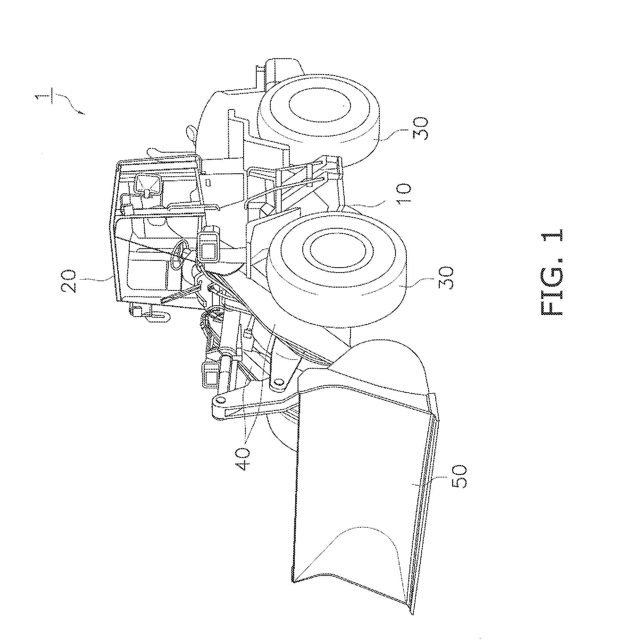
[0023]The structure of a wheel loader 1 according to an exemplary embodiment will be explained with reference to the figures. FIG. 1 is a perspective view of the wheel loader 1 according to the present exemplary embodiment.

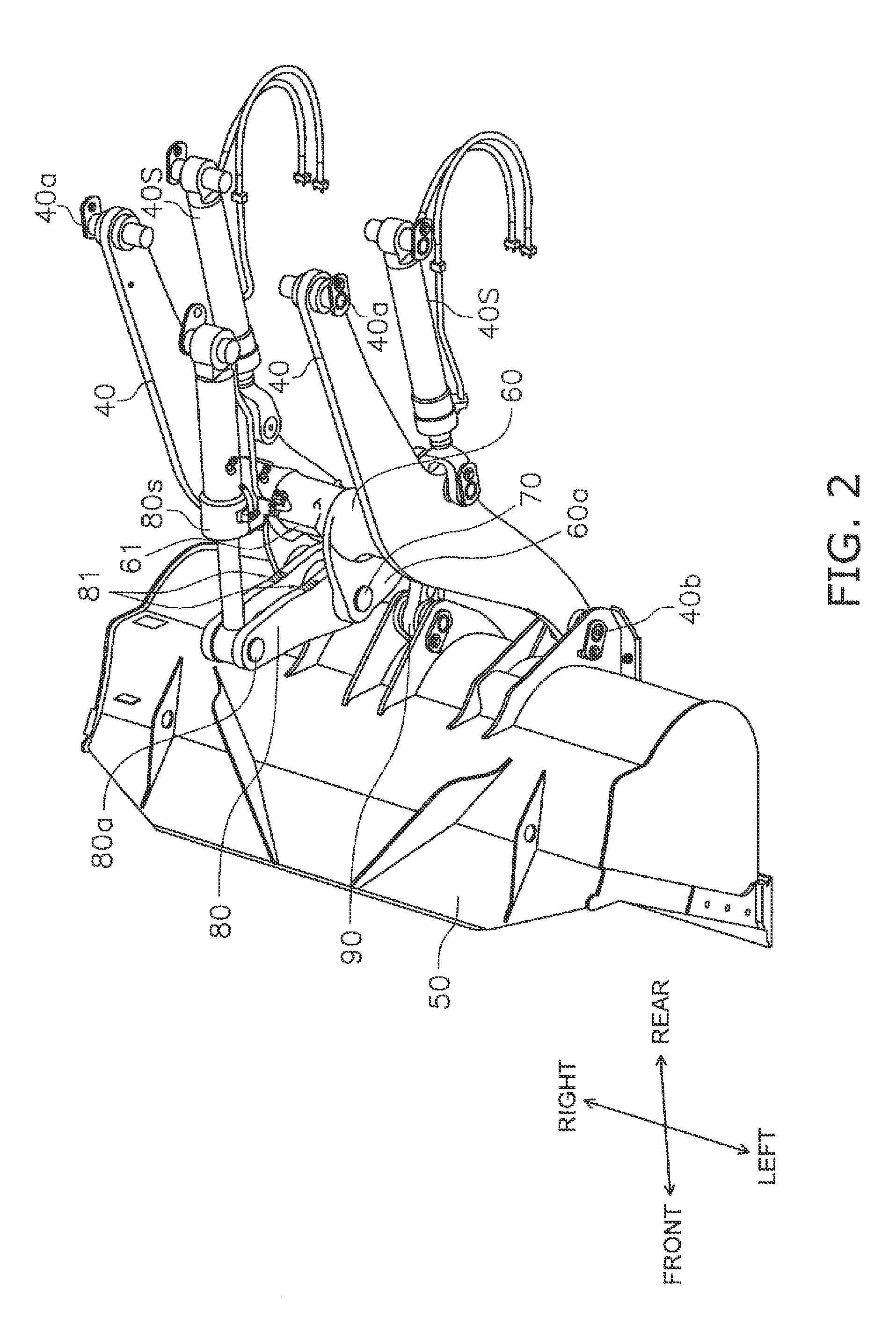
[0024]The wheel loader 1 includes a vehicle body frame 10, a cab 20, four tires 30, a pair of booms 40 and a bucket 50 (an exemplary “work imp...


PUM


Abstract

A travel damper control device includes a proximity detecting part and a valve switching part. The proximity detecting part is configured to detect that the bell crank is in proximity to the cross tube. The valve switching part is configured to switch the open / close valve into a closed position when the proximity detecting part detects that the bell crank is in proximity to the cross tube.

Description

CROSS-REFERENCE TO RELATED APPLICATIONS[0001]This application claims priority to Japanese Patent Application No. 2010-288264 filed on Dec. 24, 2010, the disclosure of which is hereby incorporated herein by reference in its entirety.TECHNICAL FIELD[0002]The present invention relates to a travel damper control device mounted on a wheel loader.BACKGROUND ART[0003]In general, wheel loaders are not provided with a suspension system for absorbing vibration of a vehicle body in order to efficiently utilize driving force for works such as digging. Therefore, chances are that a load such as earth and sand, loaded on a work implement (e.g., a bucket) attached to the tips of a pair of booms, drops due to vibration of the vehicle body during travelling.[0004]In view of the above, methods of providing a travel damper formed by boom cylinders and an accumulator communicated with the boom cylinders have been proposed (see Japan Laid-open Patent Application Publication Nos. H05-209422 and 2007-1869...

Claims


Application Information

Patent Timeline
Patent Type & Authority Patents(United States)
IPC IPC(8): E02F3/43
CPCE02F3/3411E02F9/2296E02F9/2217E02F9/2207
Inventor OTA, TOSHIYUKI
Owner KOMATSU LTD
Why Eureka
Try Eureka