

Support arm system
a technology of supporting arm and support rod, which is applied in the direction of washstand, scaffold accessories, lighting support devices, etc., can solve the problems of reducing or eliminating the flexibility of the arrangement, the stability of the supporting rod is relatively unstable, and the upward movement is still possibl
- Summary
- Abstract
- Description
- Claims
- Application Information
AI Technical Summary
Benefits of technology
Problems solved by technology
Method used
Image

Examples
first embodiment
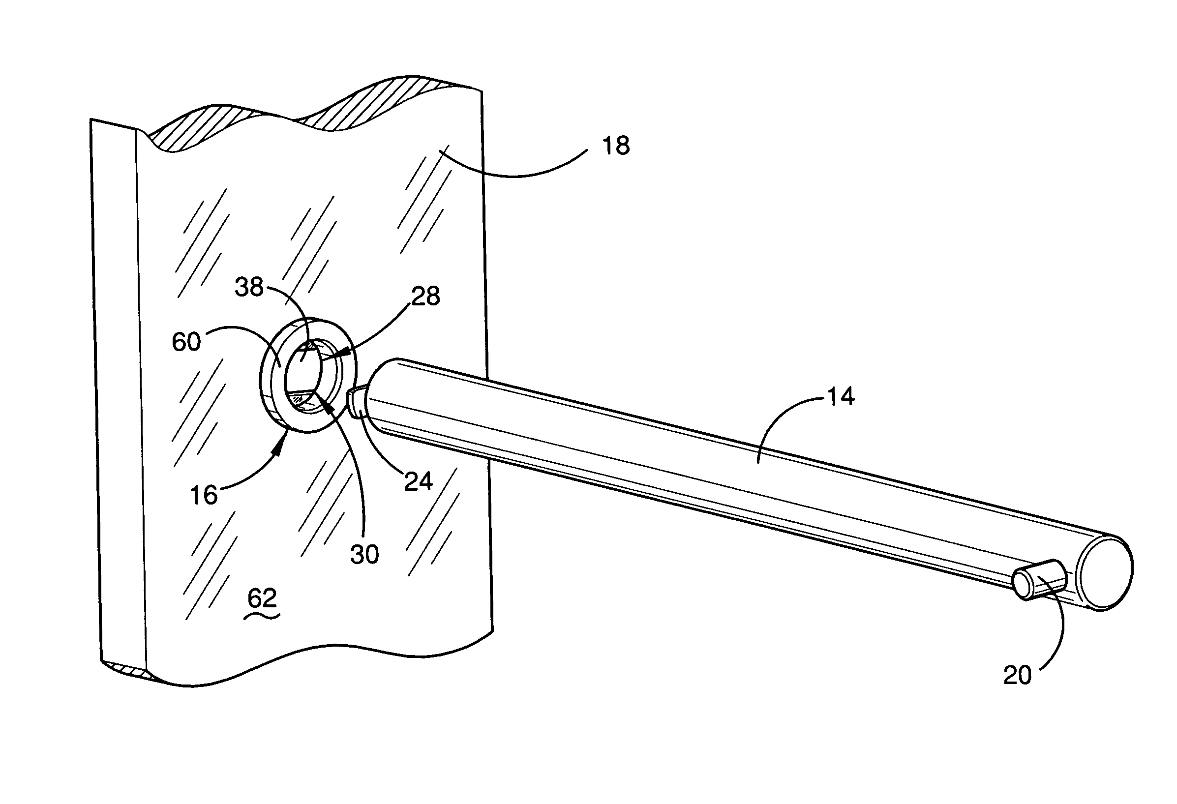
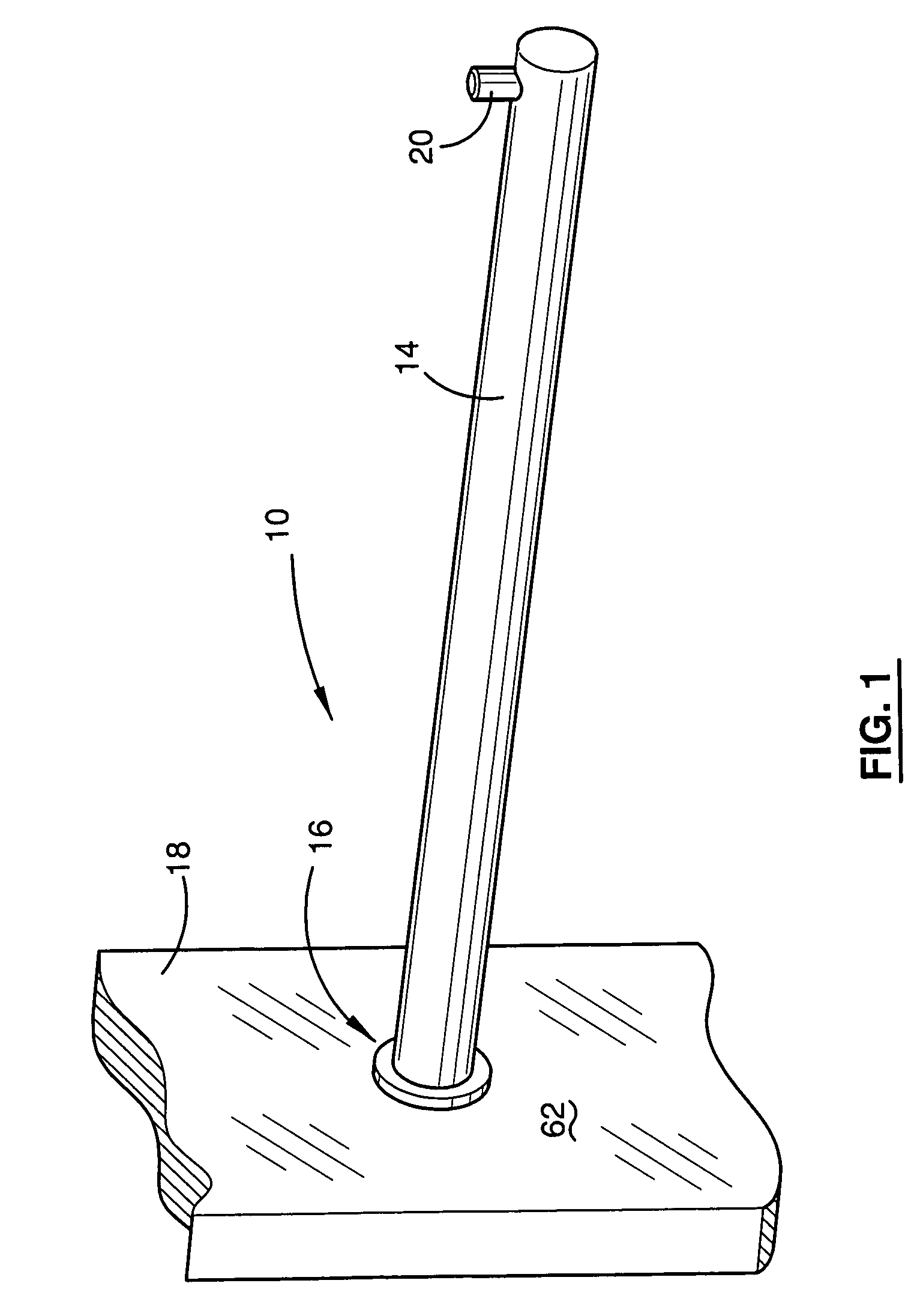
[0057]FIG. 1 shows a support arm system 10 according to the present invention, with a support arm 14 engaged in a socket 16. The socket 16 is fixed to a panel 18, which would typically be a vertical wall. The support arm 14 is of a generally elongate structure and is illustrated as being circular in cross-section. However, it will be appreciated that the present invention is not limited in this regard. The support arm 14 includes a lug 20 at its distal end, which prevents garment hangers and other suspended items from falling off the end of the support arm 14. It will be appreciated that other forms of the support arm are incorporated within the present invention. The support arm 14 may include a connection device, allowing other components to connect to the support arm.
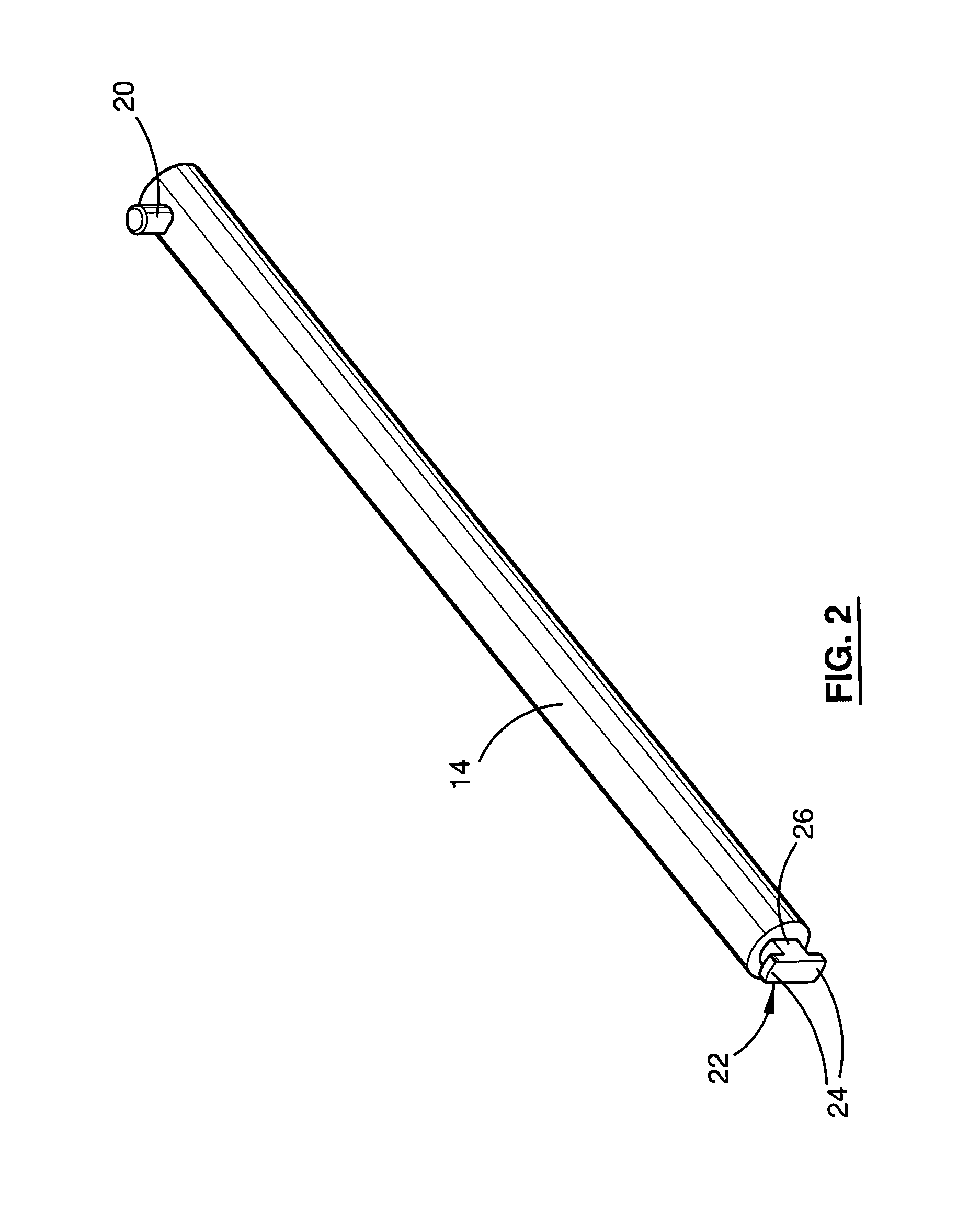
[0058]As can be seen in FIG. 2, the support arm 14 includes a T-shaped protrusion 22, axially projecting from the end of the support arm that is inserted into the socket 16. The T-shaped protrusion 22 includes two lu...
second embodiment
[0066]It will be appreciated that this invention may be used with socket and support arms that engage using an arrangement different from that described above, and is not limited to axial insertion and rotation of the support arm in the socket. Alternative embodiments of the invention are illustrated in FIGS. 10 to 26 in which the support arm, opening and gate are of rectangular profile, and in which the support arm includes a projection extending upwardly from the upper surface at the insertion end. FIGS. 10 and 11 show a support arm system 110 in use. In FIG. 10, two systems 110 are supporting a frame structure 112. In FIG. 11, a system 110 is being used as a display rack.
[0067]The support arm system 110 according to the second embodiment of the present invention includes a support arm 114 and a socket 116. The socket 116 is fixed to a vertical wall surface 118. The support arm 114 is of a generally elongate structure and is illustrated as having a square cross-section. However, ...
third embodiment
[0076]As shown in FIGS. 20, 21 and 22, a socket 116 can be used to create a double-sided display. An aperture 166 is cut into the wood panel 168, similar to that shown in FIG. 18. The thickness of the wood panel 168 is approximately double, thus allowing two housings 122 to be inserted into opposite sides. Double ended screws 174 are used to fix the two housings 122 together, omitting the need for a rear plate 154. Assembly of the gate element 126 and front cap 130 is the same as described above. FIG. 20 shows that one way of fixing the front cap 130 to the housing 122 is by snap lock tabs 131. As shown in FIG. 22, a double-sided display provides sockets 116 on both sides of the panel 168 and allows a support arm 114 to extend from both sides.
[0077]The use of the brackets 150, 152 shown in FIG. 17 allows a socket 116 according to the second embodiment to be fixed to a glass panel 176 (FIGS. 23 and 24). The brackets 150, 152 are made from a plastic, preferably rubberised, material t...
PUM
 Abstract
Description
Claims
Application Information