Process unit positioning device and image forming apparatus including the same

a positioning device and image forming technology, applied in electrographic process apparatus, instruments, optics, etc., can solve the problems of reducing the above-mentioned workability, preventing the positioning plate from being fitted smoothly, and reducing the workability in the replacement of the respective process unit, so as to improve workability

Active Publication Date: 2013-09-24
KYOCERA DOCUMENT SOLUTIONS INC
View PDF18 Cites 7 Cited by
  • Summary
  • Abstract
  • Description
  • Claims
  • Application Information

AI Technical Summary

Benefits of technology

[0013]The present invention has been made in order to solve the above-mentioned problems, and a principal object thereof is to provide a process unit positioning device which can improve workability upon attachment / detachment of respective process units and allows drum shafts to be fitted into bearing holes smoothly, and an image forming apparatus including the process unit positioning device.
[0014]Another object of the present invention is to provide an image forming apparatus which can improve workability upon attachment / detachment of respective process units by smoothly attaching a positioning plate to an apparatus main body even when the image forming apparatus has a structure provided with a roller separating / contacting mechanism.
[0016]According to the above-mentioned structure, only by supporting the pivot shaft of the holder portion on a side of the apparatus main body, the positioning plate remains held by the holder portion on the side of the apparatus main body even when the drum shafts are pulled out of the bearing holes by a pivot of the holder portion, and after the respective process units are detached, attached, and replaced, the positioning plate can be mounted in a normal position only by pivoting the holder portion in a reverse direction. Therefore, each time the respective process units are detached, attached, and replaced, it is possible to further improve workability upon the detachment, attachment, and replacement of the respective process units than before without the need to locate a mount position of the positioning plate with a sense of the hand.
[0017]Further, when the drum shafts are fitted into the bearing holes of the positioning plate by the pivot, frictional resistance caused upon contact between the bearing holes and the drum shafts and the like can be alleviated by a continuous position change of the positioning plate relative to the holder portion. Accordingly, even with a structure that causes the holder portion to pivot, the drum shafts can be fitted into the bearing holes smoothly.

Problems solved by technology

However, in the case where the positioning plate is completely separated from the apparatus main body after the positioning plate is drawn out from the respective drum shafts, the user needs to locate a fitting position of the positioning plate with a sense of his / her hand in order to fit the positioning plate onto the respective drum shafts after the replacement of the respective process units, which inhibits the positioning plate from being fitted smoothly.
This reduces workability in replacement of the respective process units.
Further, the positioning plate is placed outside the apparatus main body after the positioning plate is drawn out from the respective drum shafts, and hence a moving distance for mounting / removal of the positioning plate to / from the apparatus main body is long, which further reduces the above-mentioned workability.
Further, in the case of mounting the positioning plate to the apparatus main body, when a fitting direction of the drum shafts toward the bearing holes does not coincide with a drum shaft direction because, for example, the fitting direction is inclined toward the drum shaft direction, the drum shafts become hard to be fitted into the bearing holes due to increased frictional resistance and stress caused upon contact.
However, this structure necessitates a certain amount of force to attach the positioning plate due to a reaction force acted upon the shaft member by the attachment of the positioning plate, which inhibits attachment work from being performed smoothly.

Method used


Image

  • Process unit positioning device and image forming apparatus including the same
  • Process unit positioning device and image forming apparatus including the same
  • Process unit positioning device and image forming apparatus including the same

Examples


first embodiment

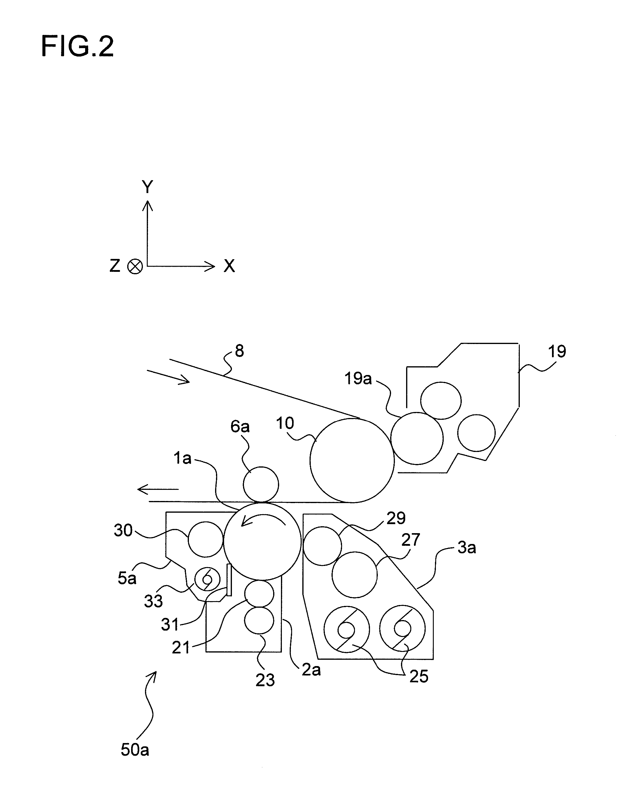
[0054]An embodiment of the present invention is described as follows with reference to the drawings. Prior to description of a process unit positioning device according to the present invention, an image forming apparatus to which the process unit positioning device is applied is first described.

[0055](1. Overall Structure of Image Forming Apparatus)

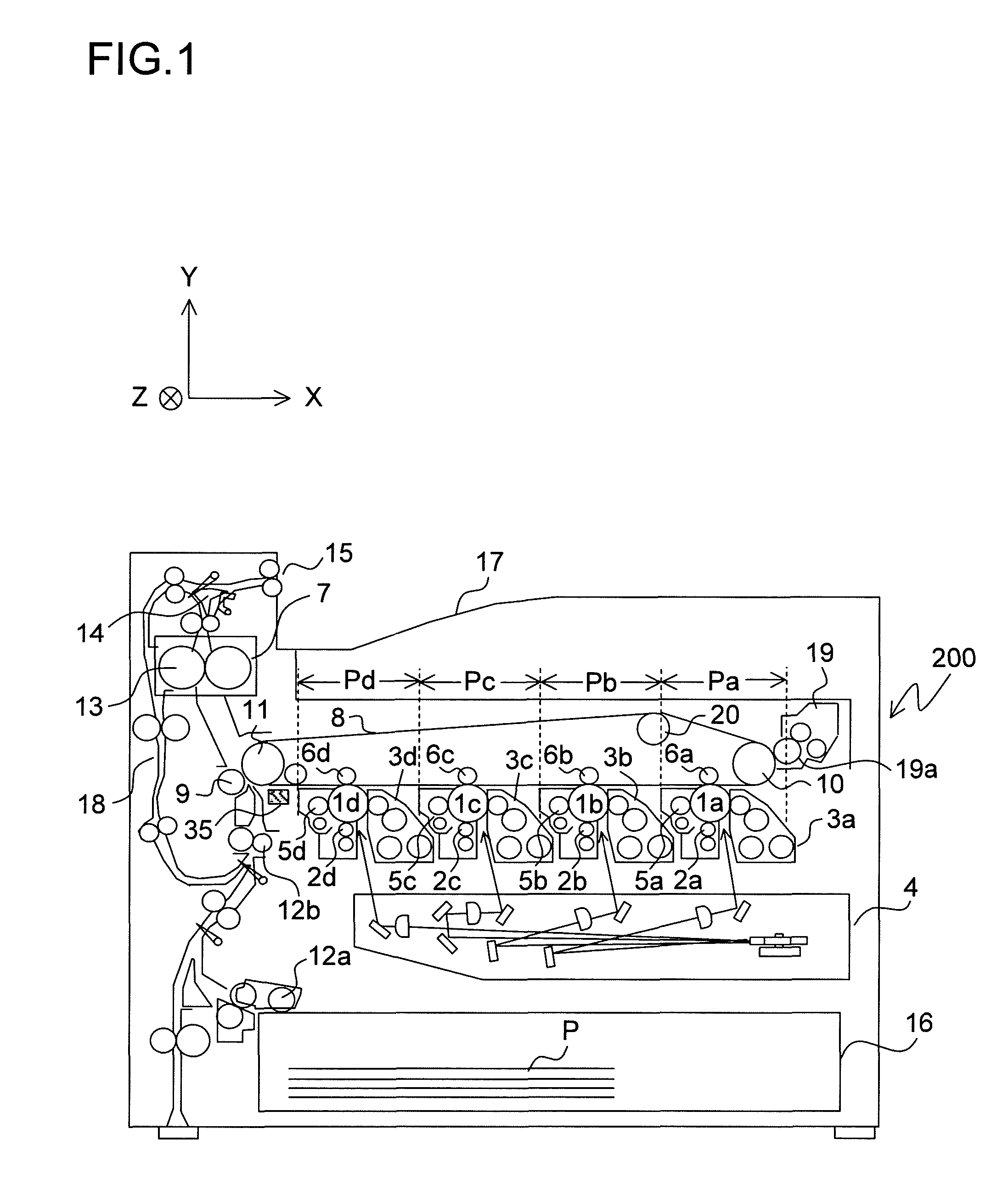
[0056]FIG. 1 is a sectional view illustrating a schematic structure of an image forming apparatus 200 according to this embodiment of the present invention. In this embodiment, the image forming apparatus 200 is structured as a four-tandem color printer for performing image formation by parallelly arranging four photosensitive drums 1a, 1b, 1c, and 1d corresponding to different four colors (yellow, cyan, magenta, and black) of toner, respectively.

[0057]In FIG. 1, four image forming portions Pa, Pb, Pc, and Pd are horizontally arrayed in order from the right inside an apparatus main body of the image forming apparatus 200. Those image for...

second embodiment

[0153]Another embodiment of the present invention is described as follows with reference to the drawings. Note that, for convenience in the following description, the same components as those of the first embodiment are denoted by the same reference symbols, and description thereof is omitted.

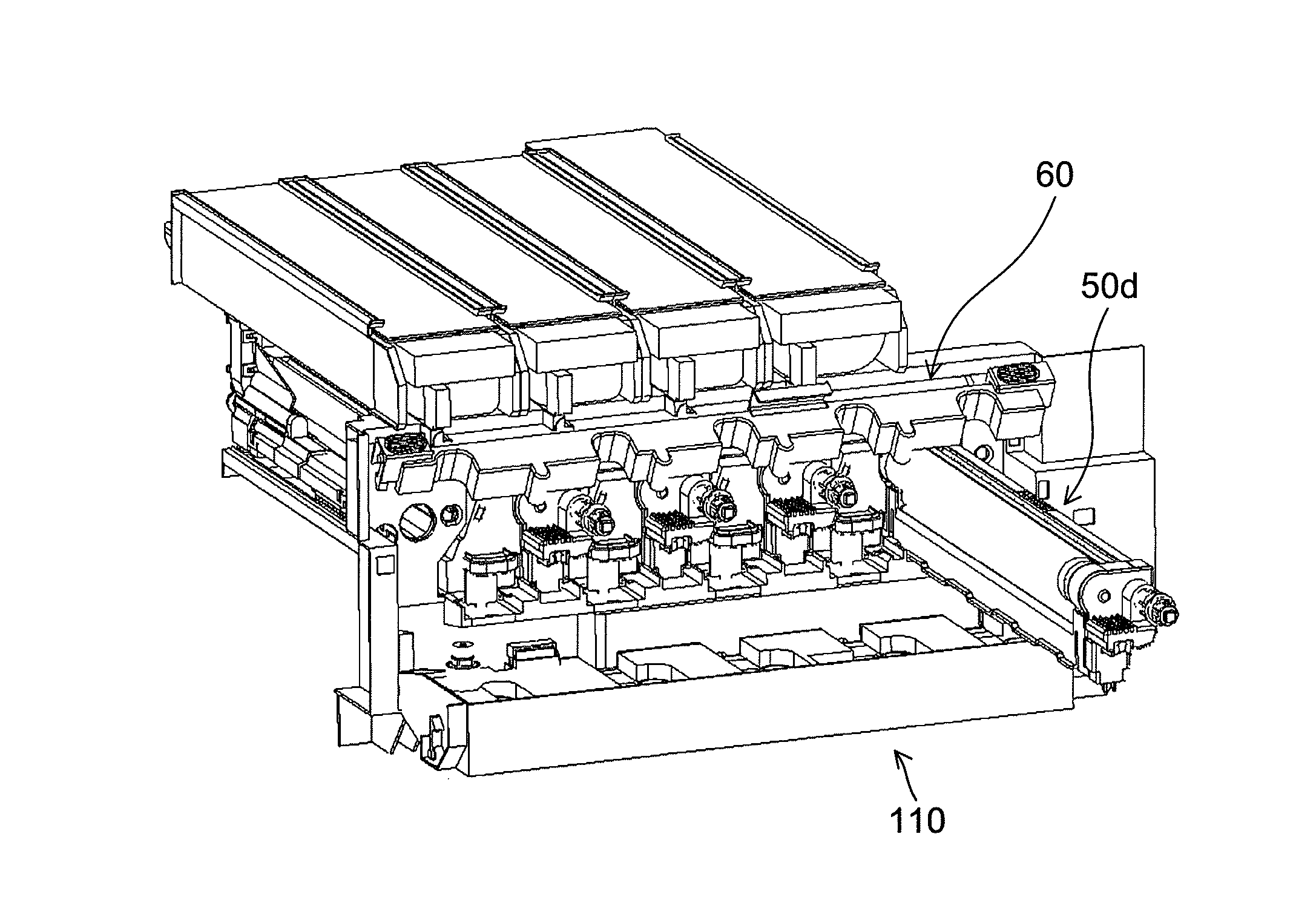
[0154]In this embodiment, the shapes and structures of the process units 50a to 50d and the developing units 3a to 3d are slightly different from those of the first embodiment. Further, the image forming apparatus 200 includes a roller separating / contacting mechanism 151 (see FIG. 26 and the like), and the positioning device 60 is structured corresponding thereto. Hereinafter, this respect is described.

[0155]FIG. 24 is a perspective view illustrating an external appearance of the process unit 50a according to this embodiment. The process unit 50a according to this embodiment has substantially the same shape as that of the first embodiment (see FIG. 6), and basic functions thereof are completely...


PUM


Abstract

Provided is a process unit positioning device which performs positioning of a plurality of process units with respect to an apparatus main body, including: a positioning plate in which bearing holes into which individual drum shafts are fitted and a fitted portion onto which positioning portion of the apparatus main body is fitted are formed; and a holder portion supported by the apparatus main body so as to be able to pivot while holding the positioning plate so that a position changes by contact between the bearing holes and the drum shafts.

Description

[0001]This application is based upon and claims the benefit of priority from the corresponding Japanese Patent Application No. 2010-015067 filed on Jan. 27, 2010 and the corresponding Japanese Patent Application No. 2010-058858 filed on Mar. 16, 2010, the entire contents of which are incorporated herein by reference.BACKGROUND OF THE INVENTION[0002]1. Field of the Invention[0003]The present invention relates to a process unit positioning device which performs mutual positioning of process units individually including photosensitive drums corresponding to different colors of toner, and an image forming apparatus which includes the process unit positioning device and forms a full-color image.[0004]2. Description of Related Art[0005]Up to now, different kinds of so-called four-tandem structure are proposed as an image forming apparatus which uses respective colors of toner, that is, yellow, cyan, magenta, and black, to form a full-color image by electrophotographic process. The image f...

Claims


Application Information

Patent Timeline
Patent Type & Authority Patents(United States)
IPC IPC(8): G03G21/16G03G21/12G03G15/00
CPCG03G21/1842G03G15/0194G03G15/011G03G15/0121G03G21/105G03G2221/1684
Inventor MORISHITA, HIROKI
Owner KYOCERA DOCUMENT SOLUTIONS INC
Why Eureka
Try Eureka