
Methods to avoid frequency locking in a multi-channel neurostimulation system using pulse placement

a neurostimulation system and multi-channel technology, applied in electrotherapy, therapy, etc., can solve the problems of ineffective or even harmful neurostimulation systems, ineffective stimulation therapy, and ineffective or even harmful stimulation therapy for tissue regions, so as to prevent temporal overlap and prevent frequency locking

Active Publication Date: 2013-09-24
BOSTON SCI NEUROMODULATION CORP
View PDF8 Cites 21 Cited by
  • Summary
  • Abstract
  • Description
  • Claims
  • Application Information

AI Technical Summary

Benefits of technology

The patent describes a method and system for preventing temporal overlap between stimulation pulses in a neurostimulation device. This is achieved by substituting each potentially overlapping pulse set with a replacement stimulation pulse that is delivered within at least one of the respective timing channels, thereby preventing temporal overlap between the stimulation pulses. Additionally, the system can predict potential charge recovery pulses and stimulation pulses that may overlap temporally, and drop or temporally shift at least a portion of the charge recovery pulse to prevent temporal overlap. This helps improve the accuracy and precision of the neurostimulation device.

Problems solved by technology

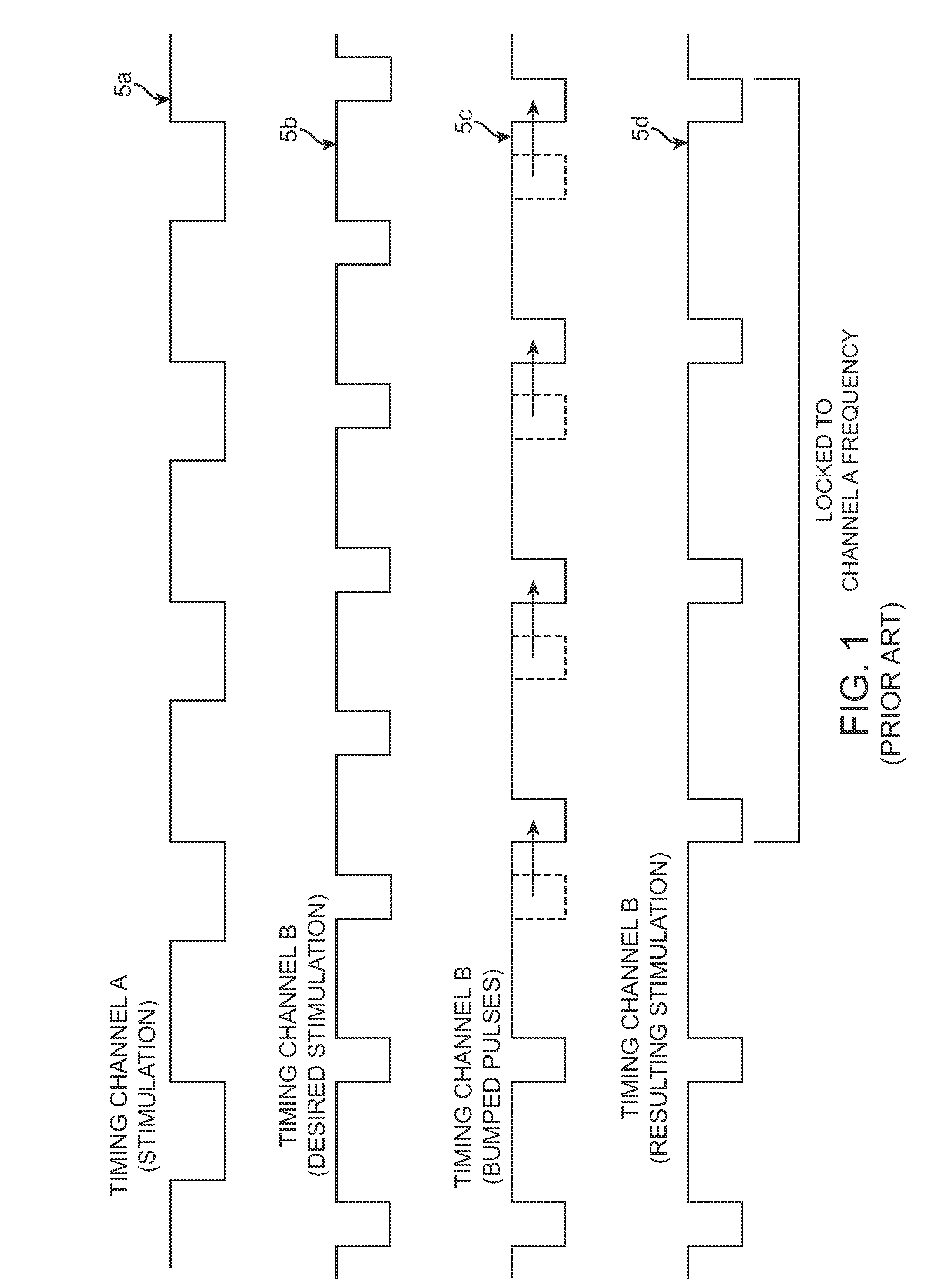
The use of multiple timing channels can often lead to problems with the electrical stimulation systems due to the potential of an overlap in pulses between two or more timing channels.
Overlapping of pulses using a common electrode can make neurostimulation systems ineffective or even harmful.
Therefore, when the occurrence of stimulation pulses is pushed out in time, stimulation therapy becomes ineffective or even harmful for tissue regions, such as brain structures to be stimulated in DBS applications, that require stimulation at specific, regular frequencies.

Method used


Image

  • Methods to avoid frequency locking in a multi-channel neurostimulation system using pulse placement
  • Methods to avoid frequency locking in a multi-channel neurostimulation system using pulse placement
  • Methods to avoid frequency locking in a multi-channel neurostimulation system using pulse placement

Examples


Embodiment Construction

[0045]The description that follows relates to a deep brain stimulation (DBS) system. However, it is to be understood that the while the invention lends itself well to applications in DBS, the invention, in its broadest aspects, may not be so limited. Rather, the invention may be used with any type of implantable electrical circuitry used to stimulate tissue. For example, the present invention may be used as part of a pacemaker, a defibrillator, a cochlear stimulator, a retinal stimulator, a stimulator configured to produce coordinated limb movement, a cortical stimulator, a deep brain stimulator, peripheral nerve stimulator, microstimulator, or in any other neural stimulator configured to treat urinary incontinence, sleep apnea, shoulder sublaxation, headache, etc.

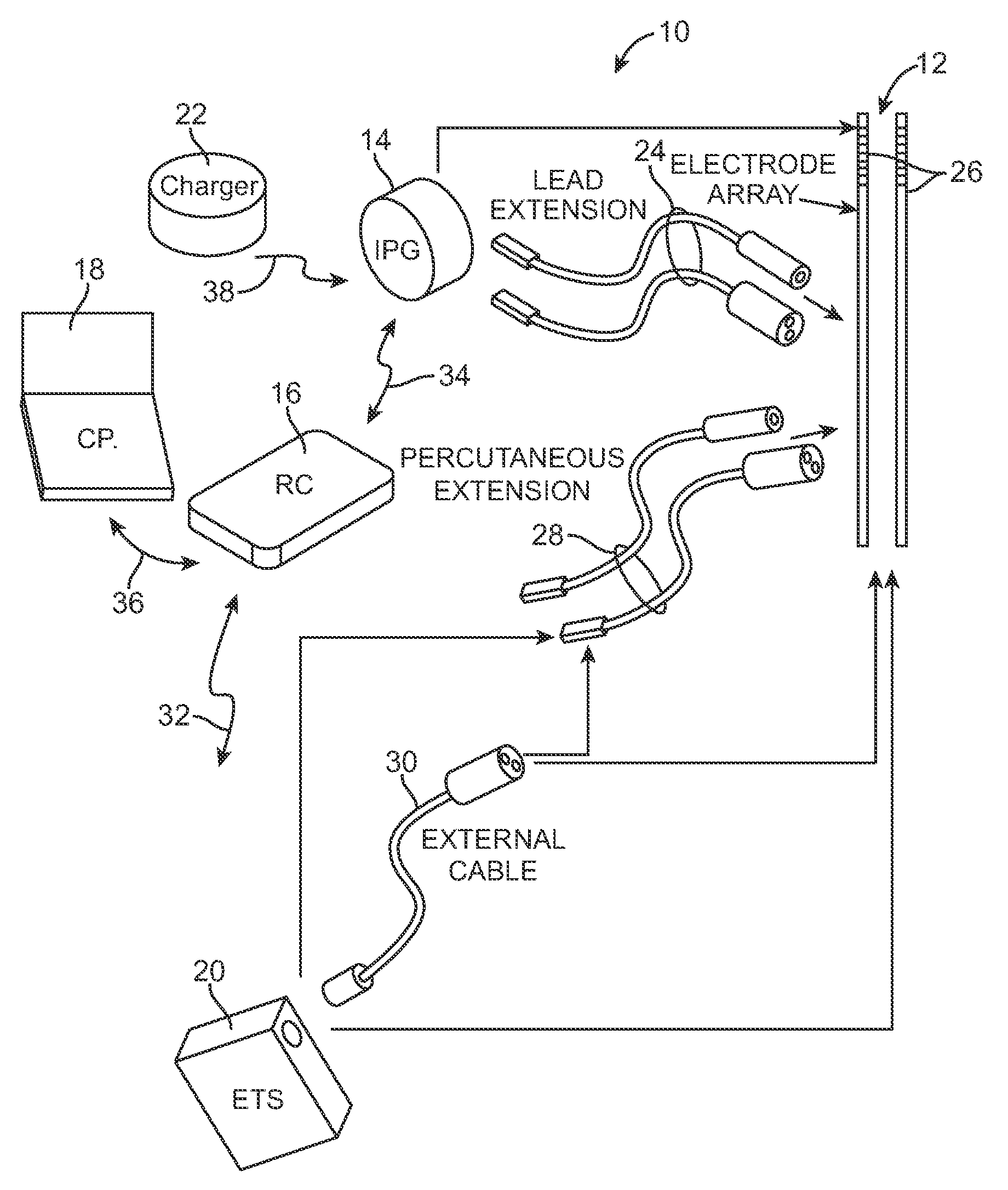
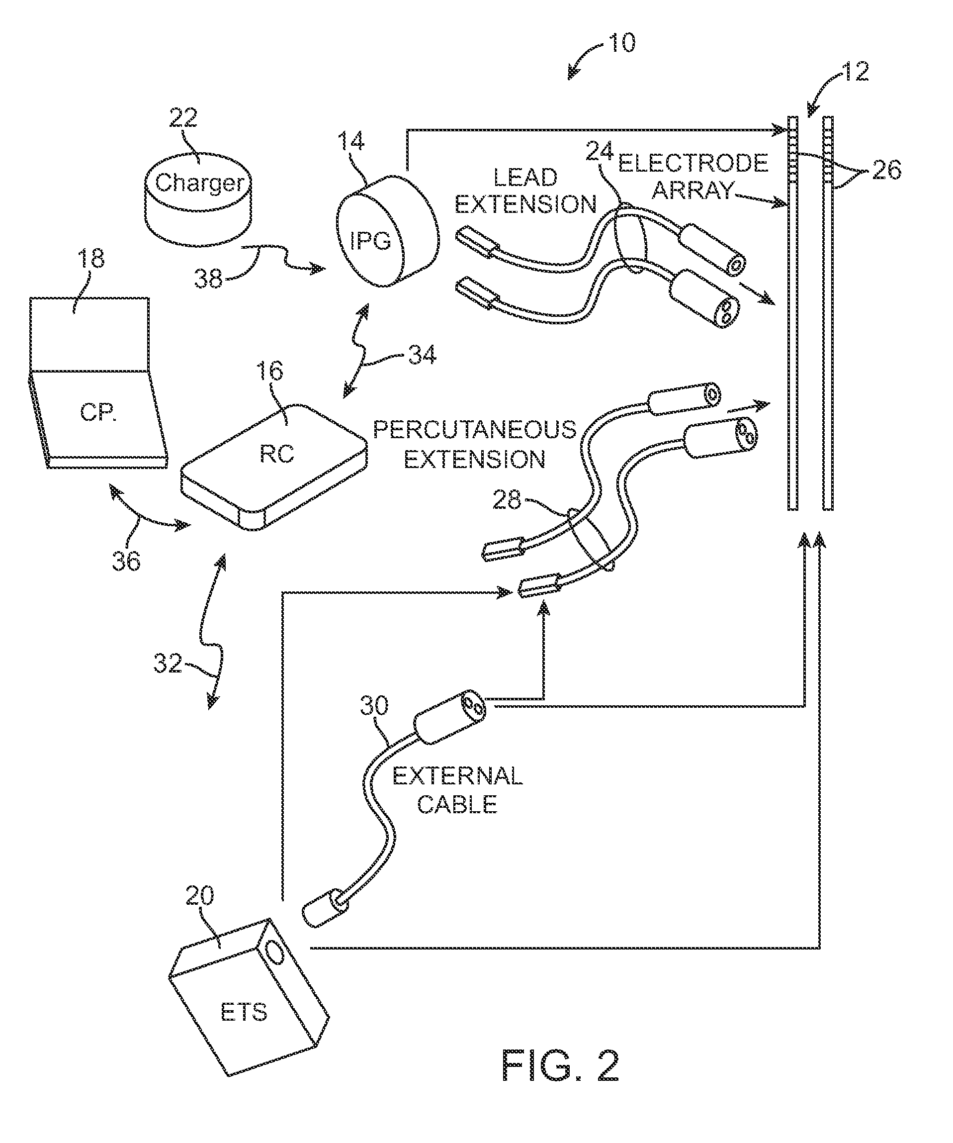
[0046]Turning first to FIG. 2, an exemplary DBS neurostimulation system 10 generally includes one or more (in this case, two) implantable stimulation leads 12, an implantable pulse generator (IPG) 14, an external remote co...


PUM


Abstract

A method and neurostimulation system for treating a patient are provided. A plurality of pulsed electrical waveforms are respectively delivered within a plurality of timing channels of the neurostimulation system, thereby treating the patient. Sets of stimulation pulses within the electrical waveforms that will potentially overlap temporally are predicted. Each of the potentially overlapping pulse sets is substituted with a replacement stimulation pulse, such that each replacement stimulation pulse is delivered within at least one of the respective timing channels, thereby preventing temporal overlap between the stimulation pulses of the respective electrical waveforms while preventing frequency locking between the timing channels.

Description

FIELD OF THE INVENTION[0001]The present invention relates to tissue stimulation systems, and more particularly, to a system and method for eliminating or reducing frequency locking in multi-channel neurostimulation systems.BACKGROUND OF THE INVENTION[0002]Implantable neurostimulation systems have proven therapeutic in a wide variety of diseases and disorders. Pacemakers and Implantable Cardiac Defibrillators (ICDs) have proven highly effective in the treatment of a number of cardiac conditions (e.g., arrhythmias). Spinal Cord Stimulation (SCS) systems have long been accepted as a therapeutic modality for the treatment of chronic pain syndromes, and the application of tissue stimulation has begun to expand to additional applications such as angina pectoralis and incontinence. Deep Brain Stimulation (DBS) has also been applied therapeutically for well over a decade for the treatment of refractory chronic pain syndromes, and DBS has also recently been applied in additional areas such a...

Claims


Application Information

Patent Timeline
Patent Type & Authority Patents(United States)
IPC IPC(8): A61N1/00
CPCA61N1/08A61N1/36071A61N1/36082
Inventor LANE, COURTNEYCARBUNARU, RAFAELBRADLEY, KERRYPETERSON, DAVID K. L.DIGIORE, ANDREWMOFFITT, MICHAEL
Owner BOSTON SCI NEUROMODULATION CORP
Learn More