
Foam soap dispenser with stationary dispensing tube

a soap dispenser and stationary technology, applied in the field of soap dispensers, can solve the problems of soap dispenser actuators being more difficult to push, poor foam products, and deformation of foam

Active Publication Date: 2013-10-01
KANFER JOSEPH S
View PDF29 Cites 32 Cited by
  • Summary
  • Abstract
  • Description
  • Claims
  • Application Information

AI Technical Summary

Benefits of technology

This patent describes a dispenser that includes a compressible liquid chamber and a compressible air chamber, which can compress and expand to dispense liquid or air. The dispenser also includes a dual actuator that can compress both chambers simultaneously. The technical effect of this invention is that the dispenser can selectively move the liquid or air to the desired chamber, allowing for easy and efficient dispensing of either liquid or air.

Problems solved by technology

However these dispensers present problems in a counter mounted environment in which the dispensing tube and spout are decoupled from the actuator.
This creates a few problems.
First, the foam can degrade as it travels through the dispensing tube, yielding a poorer foam product.
Second, pushing foam through a length of dispensing tube requires more force than pushing separate air and liquid soap sources, and this makes the actuator for the soap dispenser more difficult to push and, in the case of an electronically activated automatic soap dispenser, requires additional electric power.

Method used


Image

  • Foam soap dispenser with stationary dispensing tube
  • Foam soap dispenser with stationary dispensing tube
  • Foam soap dispenser with stationary dispensing tube

Examples


Embodiment Construction

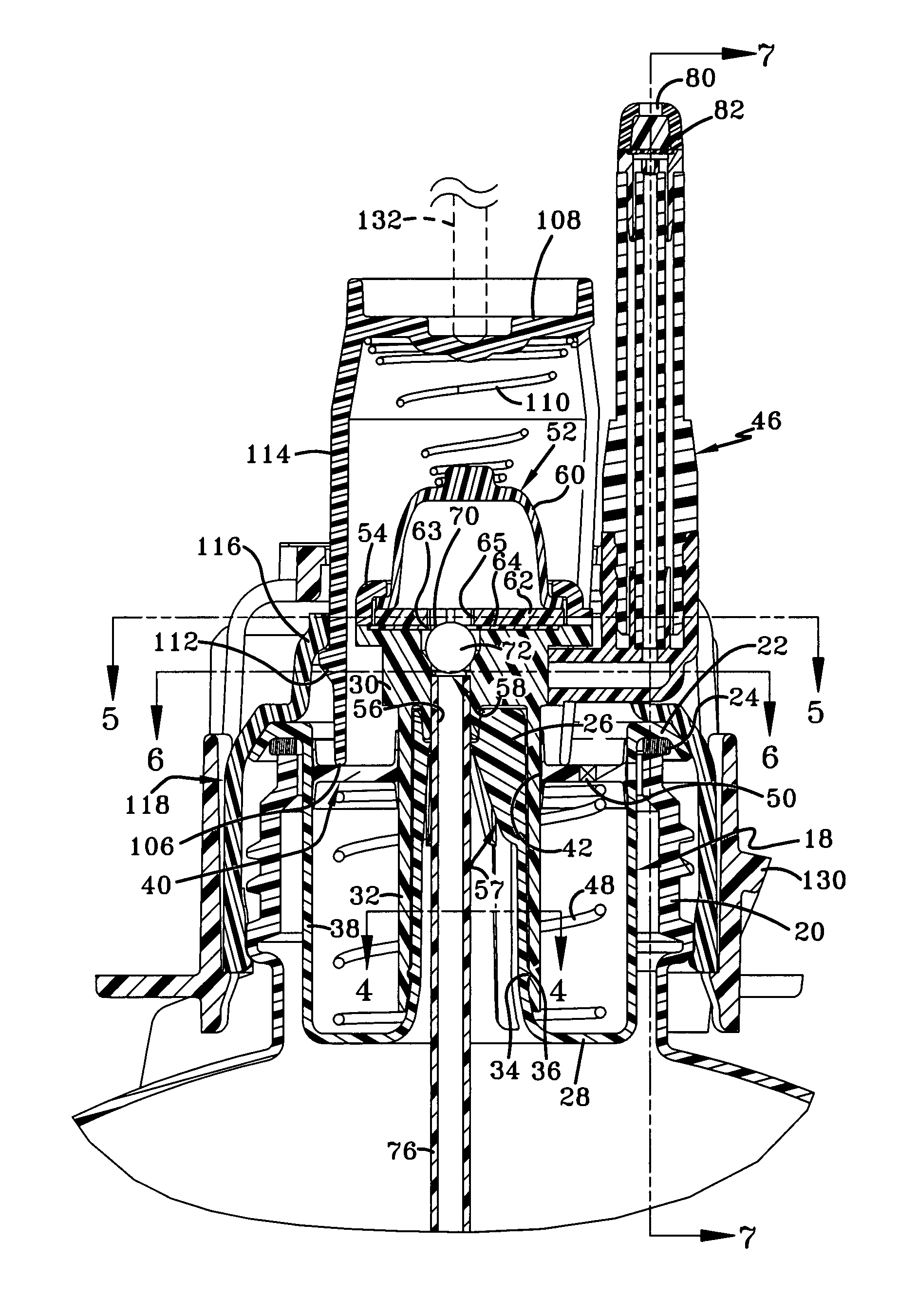
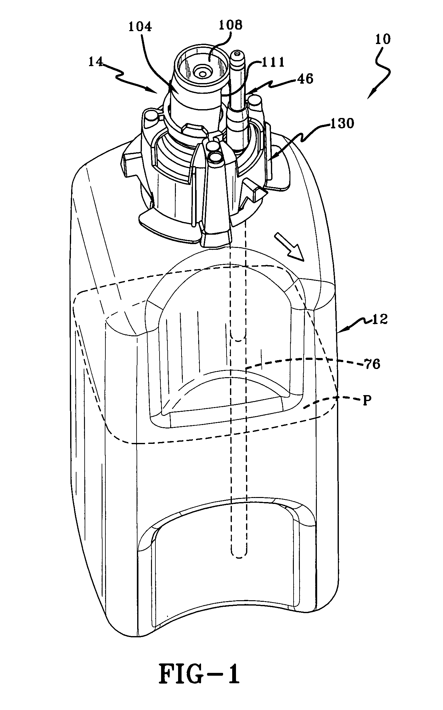
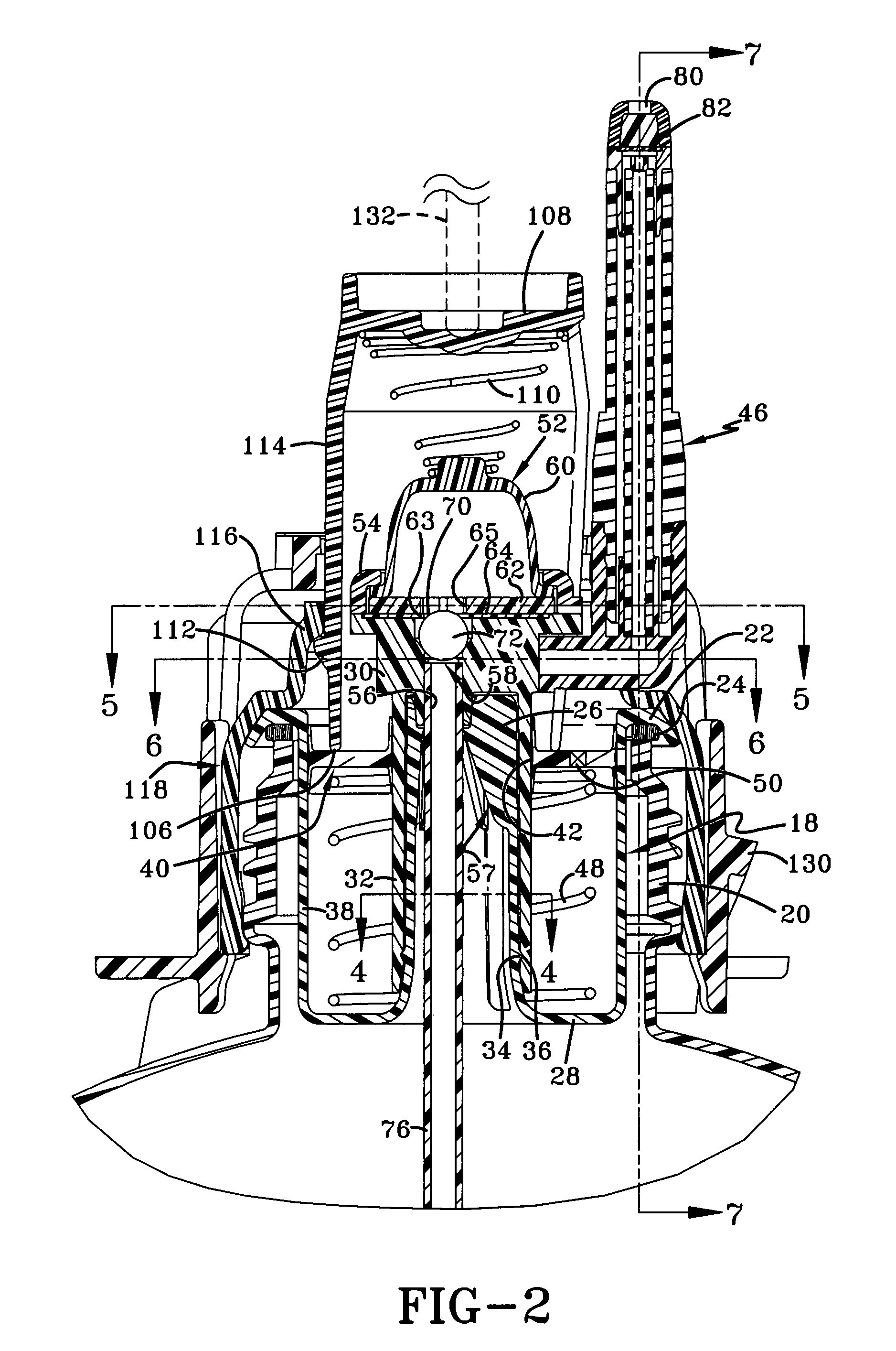
[0018]Referring now to FIGS. 1-3, an embodiment of a dispenser in accordance with this invention is shown and designated by the numeral 10. Dispenser 10 includes product container 12, which holds product P to be dispensed through actuation of a foam pump mechanism 14. Generally, the product P held within container 12 will be a liquid or other substance that can be pumped against gravity to be dispensed.

[0019]Foam pump mechanism 14 fits into container 12 at open end 16. Referring to FIGS. 2 and 3, foam pump mechanism 14 includes compressible air chamber 18, which is received in threaded neck 20 of container 12, resting on upper radial flange 22, preferably with a container gasket 24 between flange 22 and the open end 16 of threaded neck 20. Container gasket 24 serves to prevent liquid from leaking out during shipping and handling of the container 12. An axial support 26 extends upwardly from bottom wall 28 of air chamber 18. Axial support 26 receives liquid pump support 30 fitting ax...


PUM


Abstract

Dispensers are provided including pumps for dispensing a foamed product out of an outlet provided in a dispensing tube. The foam is created from the mixing of a foamable liquid and air, with separate pumps being provided for each component. The dispensing tube is stationary, although the pumps themselves have parts that must move to dispense the foamed product. A single actuator operates both the liquid and air pumps. Additionally, in some embodiments, the air pump advances air before the liquid pump advances liquid. These pumps are particularly suited to the dispensing of a foamed skin care or skin sanitizing product.

Description

TECHNICAL FIELD[0001]The invention herein resides in the art of soap dispensers. In particular embodiments, the invention relates to a foam soap dispensing system mounted to a counter, wherein a foam soap pump is mounted under a counter and receives a liquid soap container.BACKGROUND OF THE INVENTION[0002]The use of soap dispensers continues to grow as the awareness for the need for good hand hygiene practices grows. Numerous types of dispensing systems are known, including portable, hand held dispensers, wall mounted dispensers, and counter mounted dispensers. Typically, these soap dispensers dispense a predetermined amount of liquid soap upon actuation. Over the past decade or so, interest has grown in foam soap dispensers, wherein air and liquid soap are mixed to form and dispense substantially homogenous foam.[0003]Inline actuated foam soap dispensers are of particular interest because they have a number of drawbacks that can be improved upon. These dispensers include an actuato...

Claims


Application Information

Patent Timeline
Patent Type & Authority Patents(United States)
IPC IPC(8): B65D37/00B67D7/06B67D7/76
CPCA47K5/14B05B11/3097B05B11/3032B05B11/3087B05B7/0025A47K2005/1218B05B11/1032B05B11/1087B05B11/1097A47K5/06A47K5/12
Inventor CIAVARELLA, NICK E.HAYES, DAVID D.
Owner KANFER JOSEPH S
Learn More