
Light-emitting assembly and display apparatus having the same

a technology of light-emitting assembly and display apparatus, which is applied in the direction of lighting and heating apparatus, planar/plate-like light guides, instruments, etc., can solve the problems of limited receiving space for the first and second light sources, increased manufacturing costs and power consumption, and limited total thickness of the display apparatus. , to achieve the effect of reducing manufacturing costs, reducing power consumption of the light-emitting assembly, and relatively reducing the thickness of the edge-type display apparatus

Inactive Publication Date: 2013-10-01
SAMSUNG DISPLAY CO LTD
View PDF8 Cites 8 Cited by
  • Summary
  • Abstract
  • Description
  • Claims
  • Application Information

AI Technical Summary

Benefits of technology

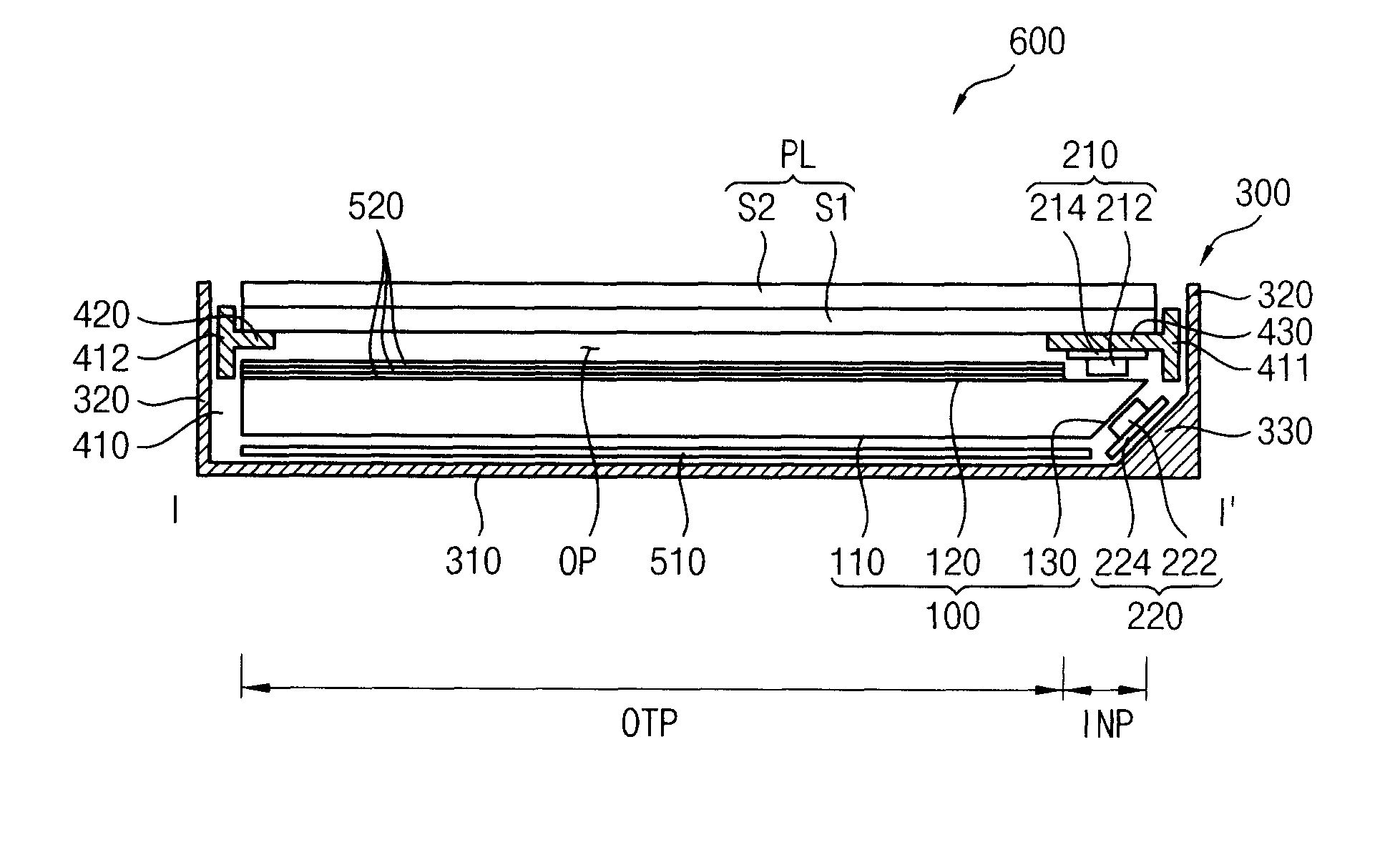
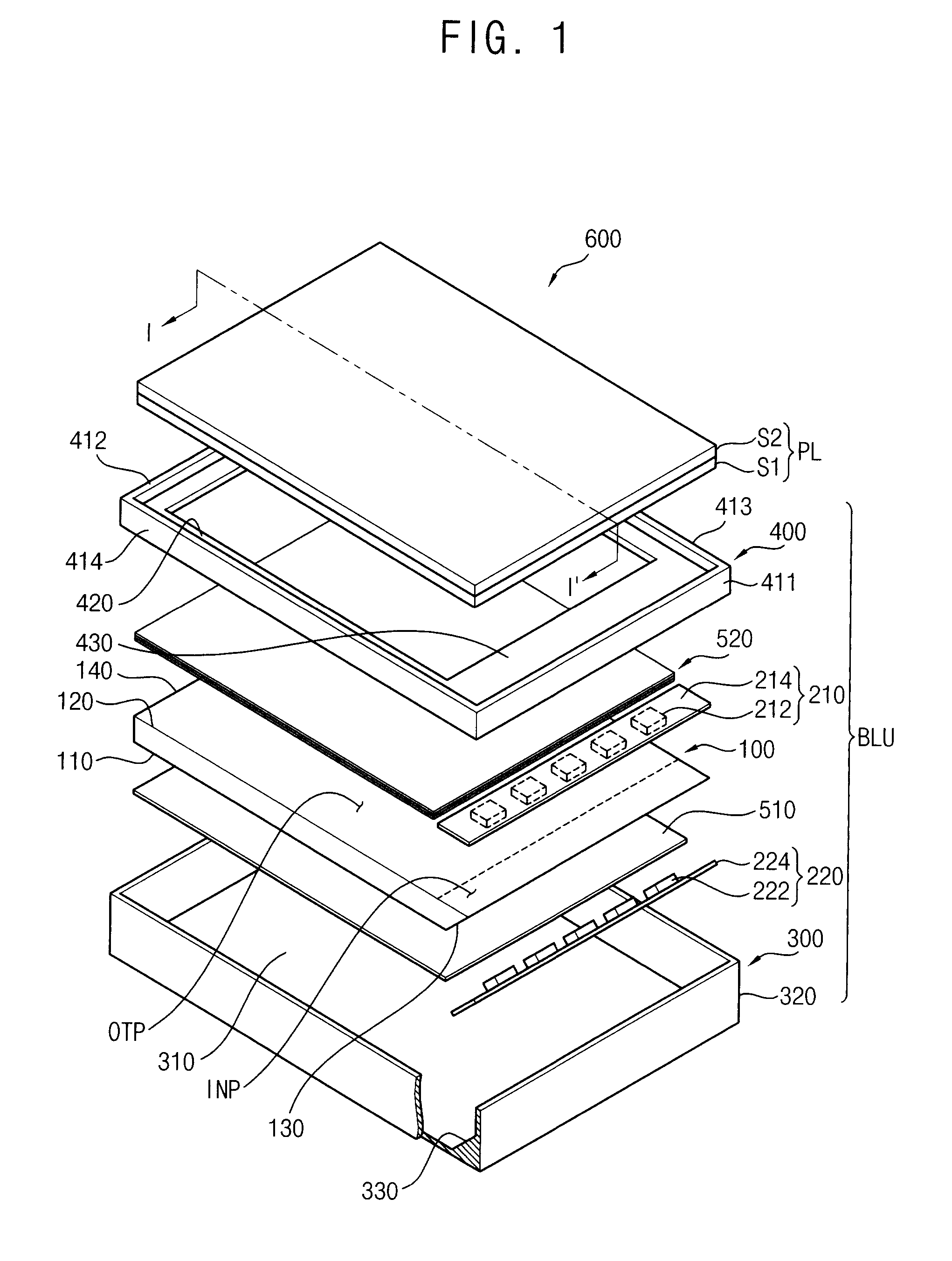
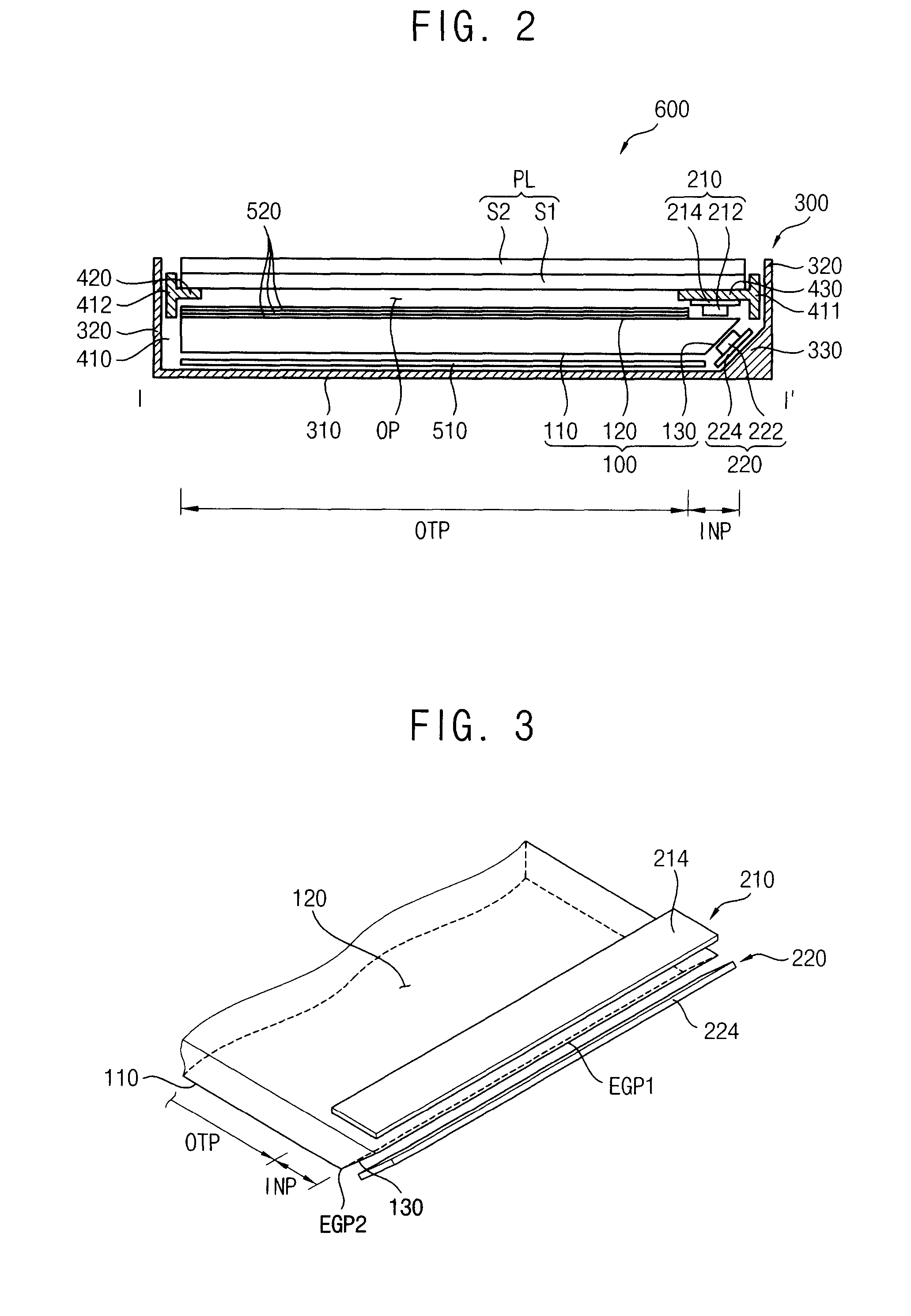
[0024]According to the invention, in a light guide plate including a first surface, a second surface, and a third surface connecting the first surface with the second surface and inclined with respect to the first surface, two different types of light-emitting modules are in a region adjacent to the third surface so that a thickness of an edge type display apparatus may be relatively decreased compared to a direct-illumination type display apparatus. Thus, a power consumption of a light-emitting assembly may be decreased, and the number of light-emitting diodes included in the light-emitting modules may be decreased to reduce a manufacturing cost.

Problems solved by technology

However, when the light-emitting assembly has the direct-illumination type, the light-emitting assembly needs to include light sources more than the light-emitting assembly having an edge-illumination type so that a manufacturing cost and a power consumption may be increased.
In addition, the light-emitting assembly of the direct-illumination type requires a receiving space for the first and second light sources under the touch screen panel so that decreasing a total thickness of the display apparatus is limited.
However, the receiving space for the first and second light sources may be limited, in the light-emitting assembly of the edge-illumination type.
In addition, the light may be hard to be uniformly provided to the touch display panel.

Method used


Image

  • Light-emitting assembly and display apparatus having the same
  • Light-emitting assembly and display apparatus having the same
  • Light-emitting assembly and display apparatus having the same

Examples


experimental example 1

[0110]A light source module LM emitting an infrared light was disposed on the second surface. After the light source module LM was controlled to provide the infrared light substantially perpendicular to the second surface, a light intensity incident into the photo sensor DET was measured.

experimental example 2

[0111]A light source module LM emitting an infrared light was disposed on the second surface. The light source module LM was controlled such that an incident angle of light incident into the second surface was about 24°, and then the light source module LM was moved in a direction MD toward an outside of the light guide plate by about 0.6 mm. After controlling and moving the light source module LM, a light intensity incident into the photo sensor DET was measured.

[0112]Result of Experiments

[0113]FIGS. 12A and 12B are conceptual cross-sectional views illustrating an efficiency of an incidence light according to a position of a first light-emitting module.

[0114]Referring to FIG. 12A, when a total intensity of light incident into the light guide plate from the light-emitting module defines “100,” an intensity of light incident into the third surface is about 80 and an intensity of light incident into the first surface is about 20. In addition, an intensity of light sensed by the photo ...


PUM


Abstract

In a light-emitting assembly and a display apparatus having the light-emitting assembly, the light-emitting assembly includes a light guide plate, a first light-emitting module and a second light-emitting module. The light guide plate includes a first surface, a second surface facing the first surface and including a light incident portion and a light exiting portion, and a third surface connecting the first surface with the second surface and inclined toward the first surface. The first light-emitting module is on the light incident portion of the second surface and emits a first light to the light incident portion. The second light-emitting module faces the third surface and emits a second light having a wavelength different from the first light, to the third surface.

Description

[0001]This application claims priority to Korean Patent Application No. 2011-0020904, filed on Mar. 9, 2011, and all the benefits accruing therefrom under 35 U.S.C. §119, the contents of which are herein incorporated by reference in its entirety.BACKGROUND OF THE INVENTION[0002]1. Field of the Invention[0003]Exemplary embodiments of the invention relate to a light-emitting assembly and a display apparatus having the light-emitting assembly. More particularly, exemplary embodiments of the invention relate to a light-emitting assembly used for a display apparatus and a display apparatus having the light-emitting assembly.[0004]2. Description of the Related Art[0005]Generally, a display apparatus includes a display panel displaying an image and a light-emitting assembly providing light to the display panel. The display panel includes a first substrate on which a switching element for driving a pixel and a pixel electrode are formed, a second substrate facing the first substrate, and a ...

Claims


Application Information

Patent Timeline
Patent Type & Authority Patents(United States)
IPC IPC(8): F21V7/04
CPCG02B6/0018G02B6/0068G02B6/002G02B6/0073G02B6/009G06F3/0412
Inventor KIM, DONG-KWONHA, JU-HWALEE, KWANG-HOONSEO, JEONG-MINKIM, WON-SEOK
Owner SAMSUNG DISPLAY CO LTD
Learn More