
Flow rate monitor for fluid cooled microwave ablation probe

a flow rate monitor and microwave ablation technology, applied in the field of microwave ablation procedures, can solve the problems of routine observation of thermal damage to most types of normal cells, unwanted heating of healthy tissue, and non-invasive use of microwave energy

Active Publication Date: 2013-10-01
TYCO HEALTHCARE GRP LP
View PDF88 Cites 20 Cited by
  • Summary
  • Abstract
  • Description
  • Claims
  • Application Information

AI Technical Summary

Problems solved by technology

However, this non-invasive procedure may result in the unwanted heating of healthy tissue.
Thus, the non-invasive use of microwave energy requires a great deal of control.
However, at slightly elevated temperatures above the approximate range of 43° C. to 45° C., thermal damage to most types of normal cells is routinely observed.
Further, defects in antenna assemblies may not be apparent except at high powers.
This is especially important for high power microwave ablation devices, where failures may result in extremely high temperatures and flying debris.
However, during operation of the microwave ablation device, if the flow of coolant or buffering fluid is interrupted, the microwave ablation device may exhibit rapid failures due to the heat generated from the increased reflected power.

Method used


Image

  • Flow rate monitor for fluid cooled microwave ablation probe
  • Flow rate monitor for fluid cooled microwave ablation probe
  • Flow rate monitor for fluid cooled microwave ablation probe

Examples


Embodiment Construction

[0024]Particular embodiments of the present disclosure are described hereinbelow with reference to the accompanying drawings; however, it is to be understood that the disclosed embodiments are merely exemplary of the disclosure and may be embodied in various forms. Well-known functions or constructions are not described in detail to avoid obscuring the present disclosure in unnecessary detail. Therefore, specific structural and functional details disclosed herein are not to be interpreted as limiting, but merely as a basis for the claims and as a representative basis for teaching one skilled in the art to variously employ the present disclosure in virtually any appropriately detailed structure.

[0025]Like reference numerals may refer to similar or identical elements throughout the description of the figures. As shown in the drawings and described throughout the following description, as is traditional when referring to relative positioning on a surgical instrument, the term “proximal...


PUM


Abstract

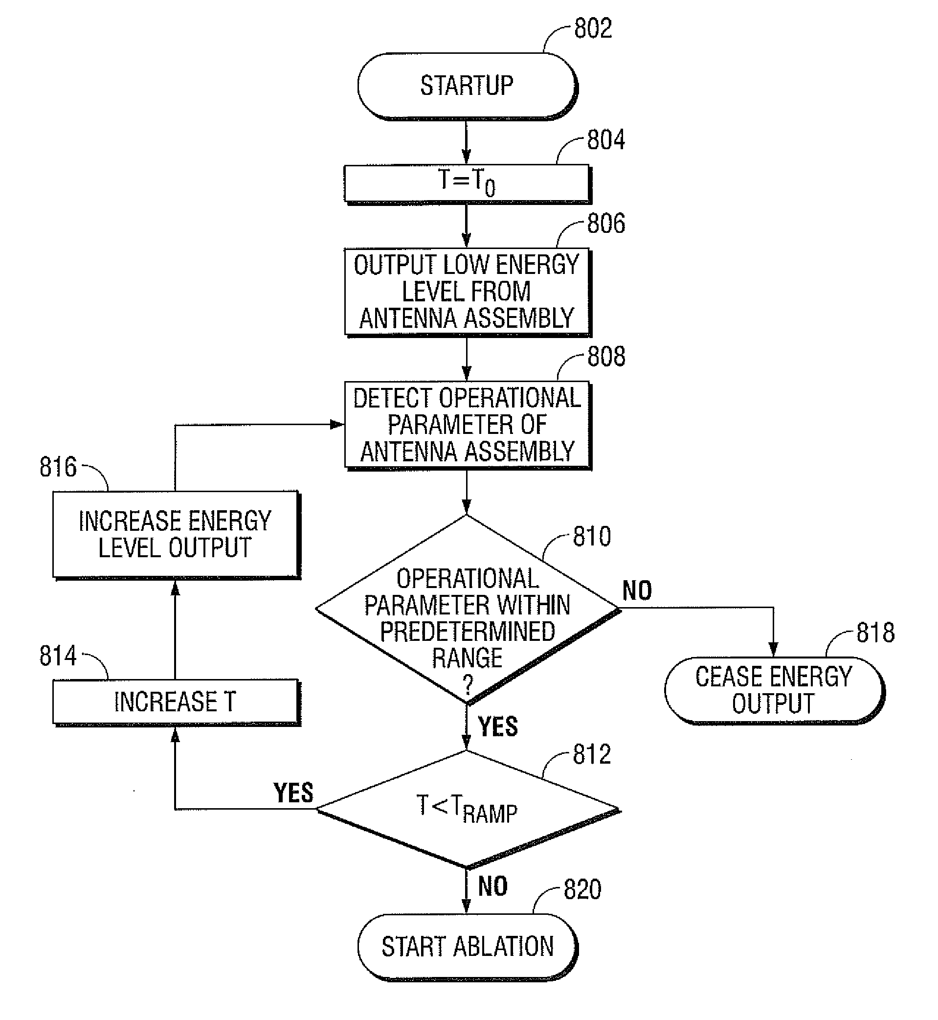
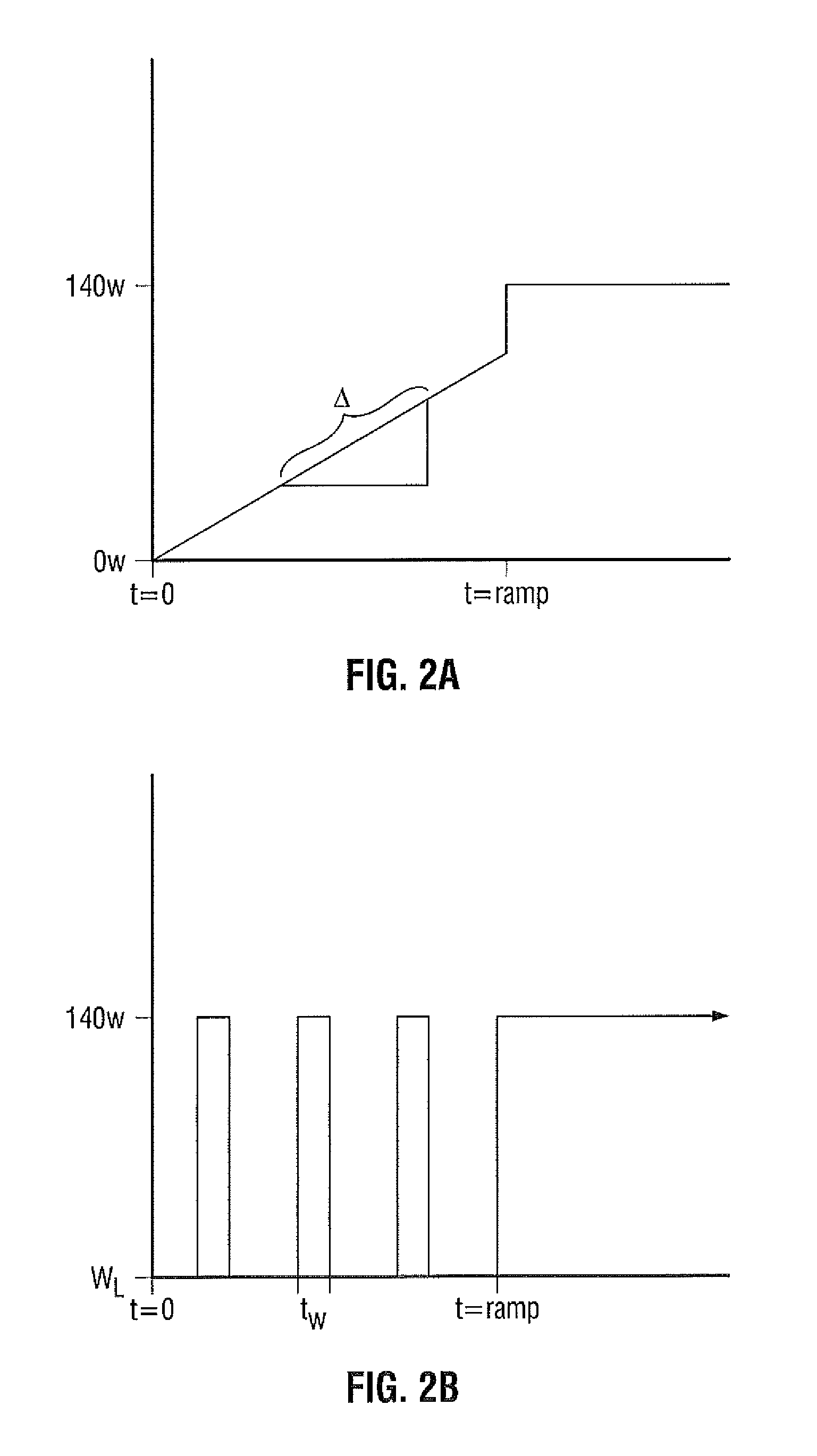
A microwave ablation system includes a generator operable to output energy and an ablation probe coupled to the generator that delivers the energy to a tissue region. The ablation system also includes a controller operable to control the generator and at least one sensor coupled to the ablation probe and the controller that detects an operating parameter of the ablation probe. The controller performs a system check by ramping up an energy output of the generator from a low energy level to a high energy level and monitors an output from the sensor at predetermined intervals of time during the system check to determine an abnormal state. The controller controls the generator to cease the energy output when the controller determines an abnormal state.

Description

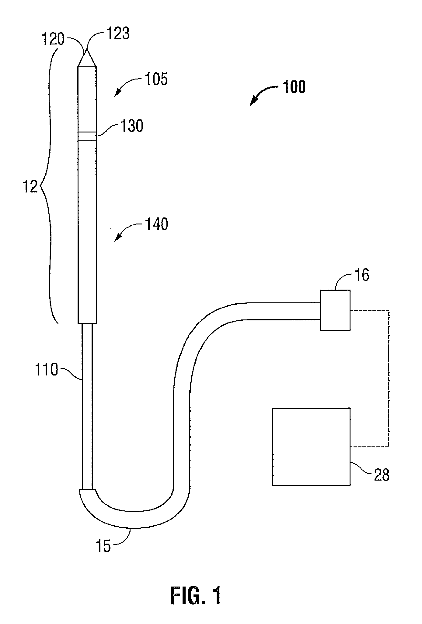
CROSS-REFERENCE TO RELATED APPLICATIONS[0001]This patent application is related to copending patent application Ser. No. 12 / 562,575 filed Sep. 18, 2009 and entitled “METHOD FOR CHECKING HIGH POWER MWA SYSTEM STATUS ON STARTUP”, copending patent application Ser. No. 12 / 566,299 filed Sep. 24, 2009 and entitled “OPTICAL DETECTION OF INTERRUPTED FLUID FLOW TO MWA ANTENNA”, copending patent application Ser. No. 12 / 568,972 filed Sep. 29, 2009 and entitled “FLOW RATE MONITOR FOR FLUID COOLED MICROWAVE ABLATION PROBE” and copending patent application Ser. No. 12 / 569,171 filed Sep. 29, 2009 and entitled “FLOW RATE MONITOR FOR FLUID COOLED MICROWAVE ABLATION PROBE”.BACKGROUND[0002]1. Technical Field[0003]The present disclosure relates generally to microwave ablation procedures that utilize microwave surgical devices having a microwave antenna which may be inserted directly into tissue for diagnosis and treatment of diseases. More particularly, the present disclosure is directed to a system an...

Claims


Application Information

Patent Timeline
Patent Type & Authority Patents(United States)
IPC IPC(8): A61B18/18
CPCA61B18/1815A61B2018/00023A61B2018/1861A61B2018/1869
Inventor BRANNAN, JOSEPH D.PETERSON, DARIONBONN, KENLYN S.WILLYARD, RICHARD A.
Owner TYCO HEALTHCARE GRP LP
Learn More