
Floating plane touch detection system

a detection system and floating plane technology, applied in the field of floating plane touch detection system, can solve the problems of not being on the market any longer, devices that have never achieved commercial success, and are not easy to detect, etc., to achieve accurate, sensitive, compact and low-cost solution, and mitigate xy friction. , the effect of improving the detection of z-forces

Inactive Publication Date: 2013-10-01
ANGLIN NOAH L +1
View PDF36 Cites 67 Cited by
  • Summary
  • Abstract
  • Description
  • Claims
  • Application Information

AI Technical Summary

Benefits of technology

This solution provides accurate, sensitive, and cost-effective touch detection with improved manufacturing tolerances, maintaining image quality and enabling multi-touch capabilities.

Problems solved by technology

However, the device never achieved commercial success and is not on the market any longer.
It's possible, that the lateral forces caused a problem.
Force-based touch devices are prone to certain specific types of problem or failure.
Among others, the following problems have plagued many implementations of force-based touch devices: extremely small tolerances required for the mechanical build-up; friction and other interfering lateral forces are common, and difficult to detect and counter; extraneous items required to accomplish a “touch” surface, such as extra planes, strings and films, are expensive and difficult to manufacture; extraneous items take up space (for example, in an LCM stack-up), and add cost; a complicated mechanism may be required to keep the touch surface and the bottom surface co-planar; low accuracy and low sensitivity issues due to the interfering forces.
Touch screens produced this way have certain limitations, such as a costly “layer” of film over their displays in order to provide feedback information.
Adding various layers to the devices adds to their cost and limits transmissivity of the display, thus diminishing the quality of the transmitted image.

Method used


Image

  • Floating plane touch detection system
  • Floating plane touch detection system
  • Floating plane touch detection system

Examples


Embodiment Construction

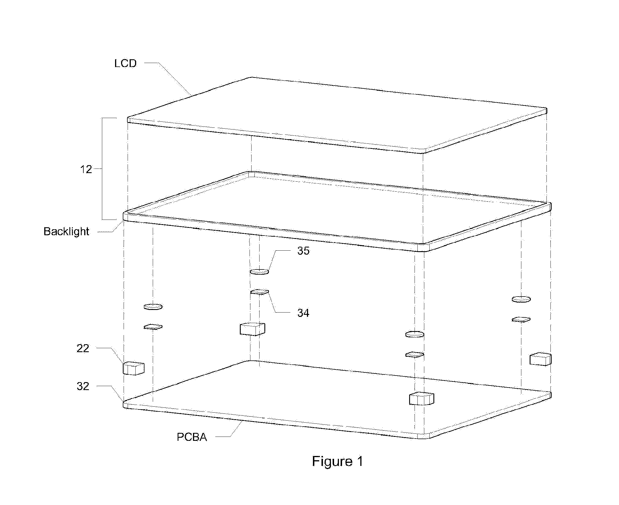
[0011]The floating plane system introduced here uses a flexible mounting material (medium) to suspend or “float” the touch surface in a manner that accommodates XY friction and improves detection of the Z-force.

[0012]It provides for wider “co-planar” tolerances, simplifying the manufacturing process. For example, a plane is defined by three points, while typical touch screens are mounted at four corners, and in ever-thinner designs. Thinner designs dictate ever-smaller touch deflection differences. Any design attempting to separate touch and sensor planes at four points must calibrate those four mounting points (frequently force sensors) with extreme precision, making the necessary tolerances increasingly manufacturing-intensive.

[0013]It uses non-contact sensors that measure the vertical displacement of the touch surface, again diminishing unwanted lateral forces usually present in force-based devices.

The system can adapt existing planes within a typical LCD display assembly, and av...


PUM


Abstract

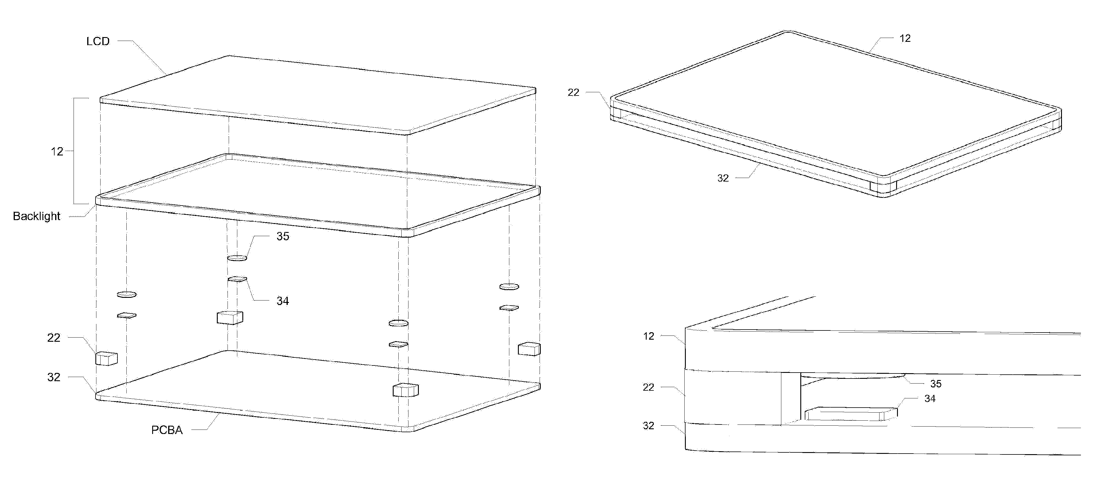
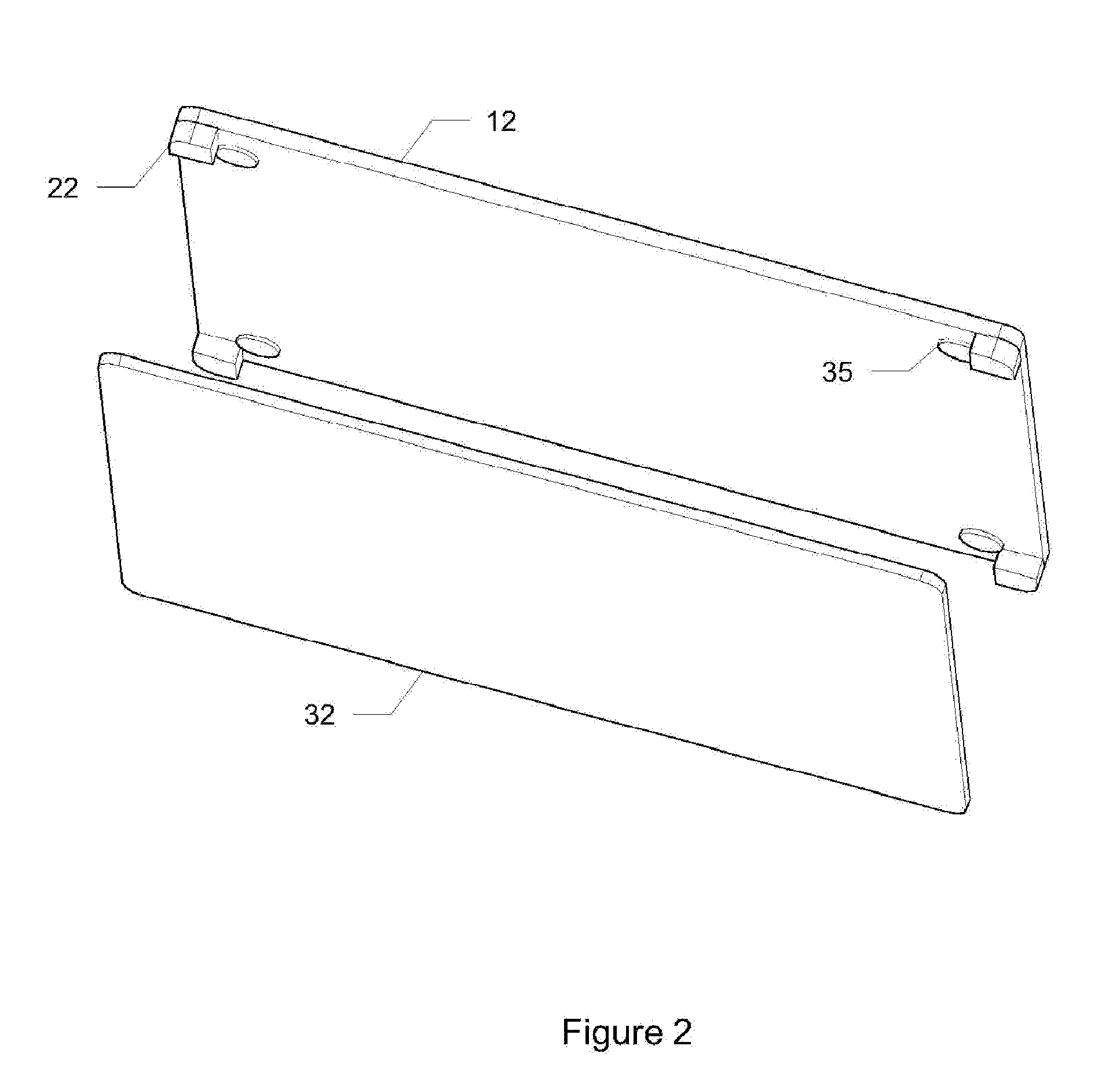
A force / displacement touch device, this invention employs a base-plane 32 and flexible mounting material to suspend, or “float,” a non-rigidly mounted touch-plane 12, and uses sensors at each mounting point 22 to measure Z-axis deflection of the floating touch-plane 12. The system adapts existing planes in typical LCD assemblies to implement touch screens. This floating touch detection system provides an accurate, sensitive, compact and low-cost solution. It mitigates XY friction to improve detection of Z-forces. This approach provides latitude in locating sensors 34, allows for additional mid-plane sensors, enables greater accuracy and resolution, and adds features such as “multi-touch” sensitivity. This touch system is defined as a unique and novel ‘floating’ co-planar assembly of a touch-plane 12 to a base-plane 32, which uses a flexible material 22 or medium to define a consistent resting air gap, and then senses and measures any deflection from the co-planar resting position, using any among a broad variety of sensor types.

Description

CROSS-REFERENCE TO RELATED APPLICATIONS[0001]This application claims the benefit of U.S. Provisional Application No. 61 / 207,775 filed Feb. 17, 2009.BACKGROUND[0002]Touch devices have become increasingly common with technological improvements in communication devices, which require user interface improvements. Various ways of detecting and interpreting touch have been explored for the last fifty years. Today, touch screens are used in a variety of devices, small (cell-phones and PDAs), medium (laptops, monitors, ebooks), large (POS terminals, kiosks and ATMs) and even very large touch panels (over 1 meter) for rugged environments. Across the spectrum of touch screen devices, flat panel displays are popular, especially LCDs. But touch devices have been plagued by various mechanical problems that still present a challenge to engineers and manufacturers.DESCRIPTION OF PRIOR ART[0003]The concept of locating a touch point by recording the applied force was researched and documented initia...

Claims


Application Information

Patent Timeline
Patent Type & Authority Patents(United States)
IPC IPC(8): G06F3/041
CPCG06F3/0414G06F3/04142
Inventor ANGLIN, NOAH L.MALINIAK, KRYSTYNA
Owner ANGLIN NOAH L
Learn More