Brake system for a vehicle and method for operating a brake system for a vehicle

a brake system and vehicle technology, applied in the direction of braking components, position/direction control, special data processing applications, etc., can solve the problems of two brake control devices and/or wheel actuator devices failing within a short time interval, and achieve the effect of safe reduction of vehicle speed

Active Publication Date: 2013-10-01
ROBERT BOSCH GMBH
View PDF25 Cites 6 Cited by
  • Summary
  • Abstract
  • Description
  • Claims
  • Application Information

AI Technical Summary

Benefits of technology

[0009]The present invention is based on the realization that at least one wheel actuator device of a brake system for exerting a braking torque on an associated wheel may be developed in such a way that it detects when an operability of other components of the brake system no longer exists and, if indicated, automatically exerts a specified braking torque on the associated wheel. Such a wheel actuator device is always able to initiate an automatic braking operation of the vehicle in situations in which a braking operation of the vehicle controlled by the driver is no longer possible due to a failure of several components of the brake system. The brake system according to the present invention and the corresponding method thus ensure a safe reduction of the speed of the vehicle for avoiding accidents in the event of the occurrence of severe malfunctions in several components of brake system.
[0012]The brake system according to the present invention has a simple system architecture having two brake circuits. The present invention is additionally based on the realization that in conventional brake systems having only one brake control device, the brake control device represents a bottleneck for the availability and safety of the power-operated brake system (brake-by-wire system).
[0014]In an example embodiment of the brake system, each of the two brake control devices is designed to check its operability itself and to switch itself to the inactive state when an impairment of its operability is detected and / or to output a warning signal to the other brake control device and / or at least one of the wheel actuator devices. Likewise, each of the four wheel actuator devices may be designed accordingly. The brake control devices and / or the wheel actuator devices are designed to be fail-silent. They check their current operability and in response to detecting an impairment of their operability transition into a state in which they no longer influence the other components of the brake system. This improves the safety of such a brake system.

Problems solved by technology

For this purpose, failures of central brake control devices or wheel actuator devices, which occur at a time interval of few computing cycles, may be detected as separate failures.
The probability that two brake control devices and / or wheel actuator devices fail within this brief time interval is very low.

Method used


Image

  • Brake system for a vehicle and method for operating a brake system for a vehicle
  • Brake system for a vehicle and method for operating a brake system for a vehicle
  • Brake system for a vehicle and method for operating a brake system for a vehicle

Examples


Embodiment Construction

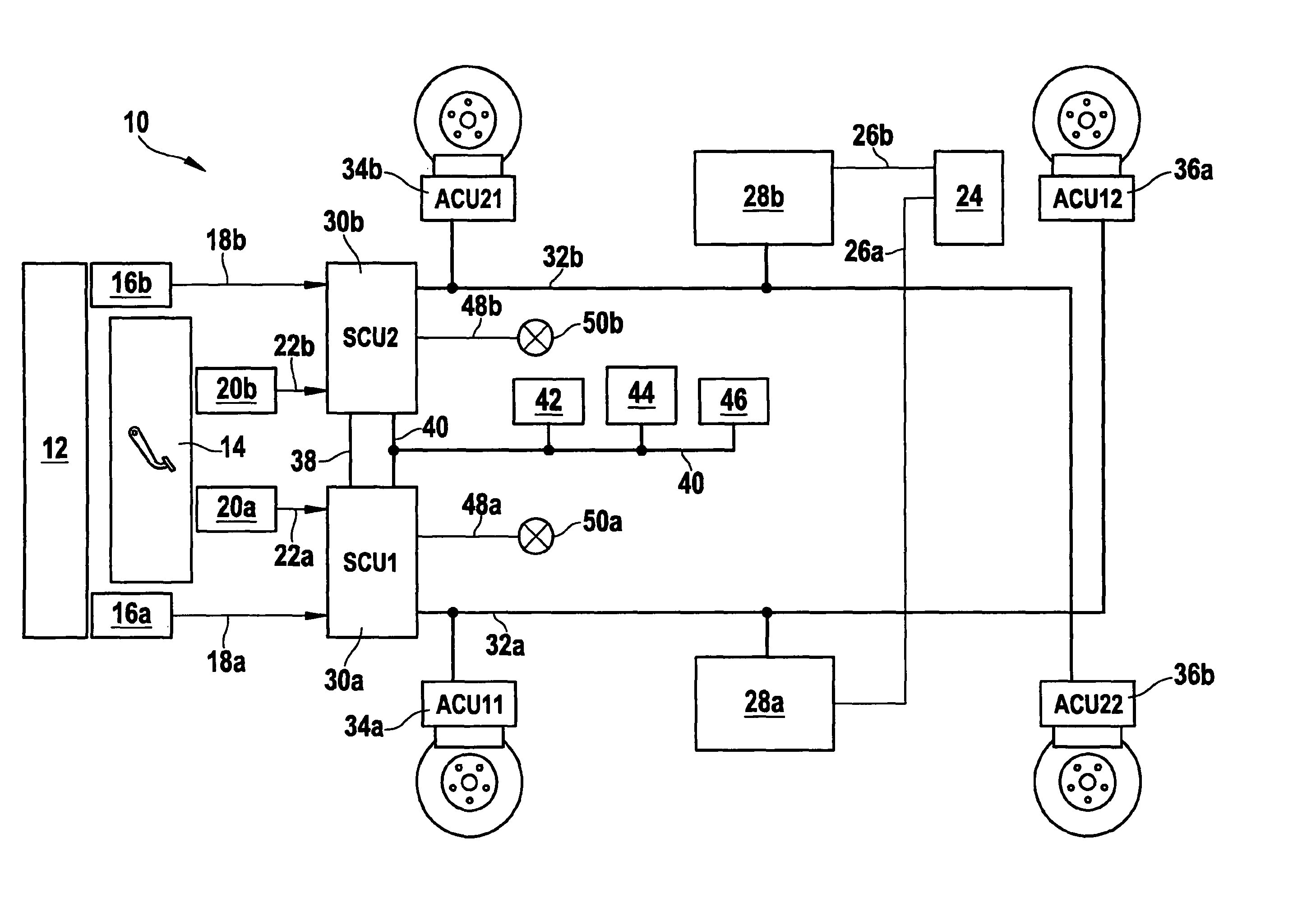
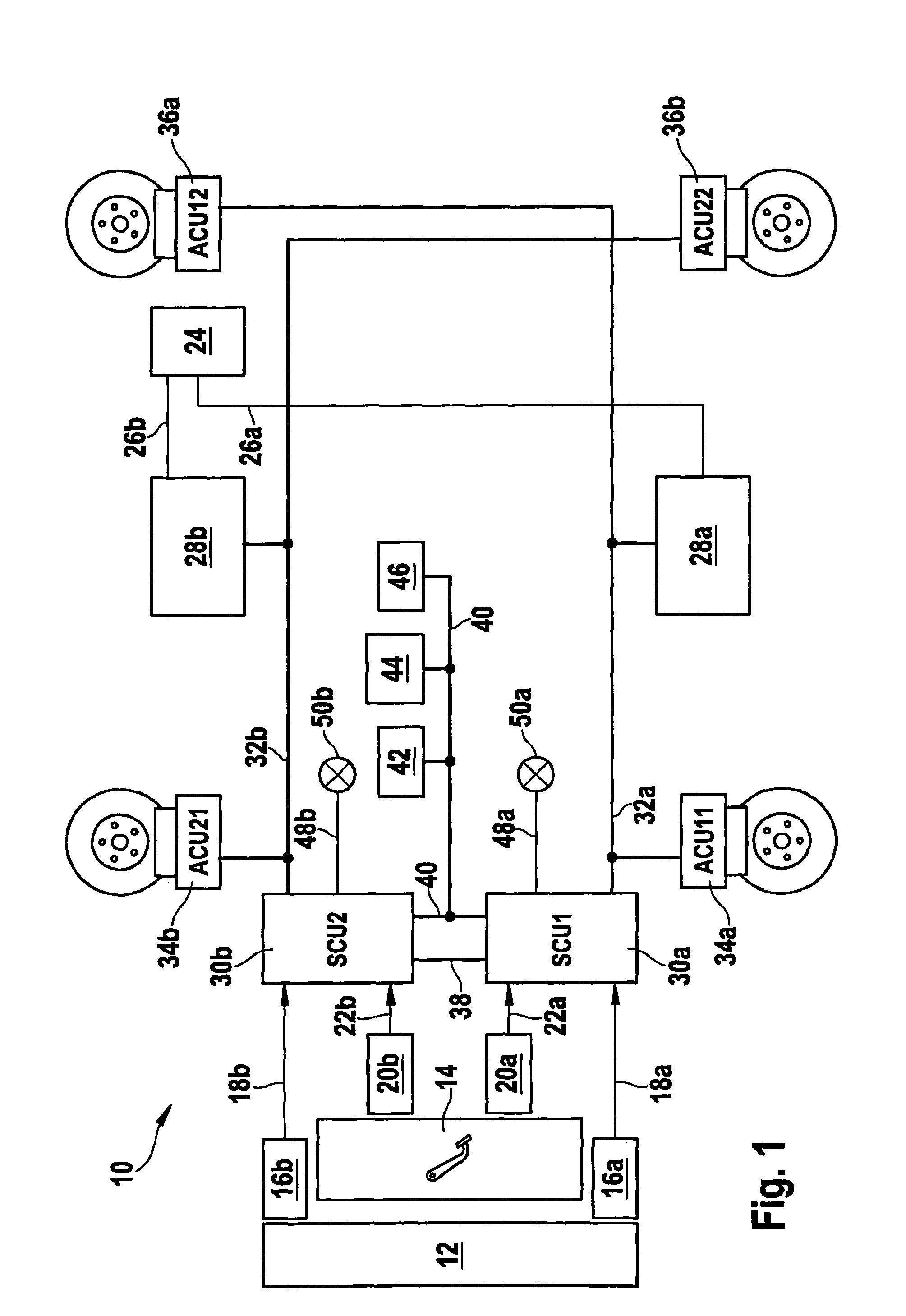
[0029]FIG. 1 shows an example embodiment of the brake system according to the present invention. The represented brake system 10 is developed electromechanically having two separate brake circuits, which are used to brake the four wheels of a vehicle. As will be explained in more detail below, brake system 10 has a diagonal brake circuit distribution.

[0030]Brake system 10 is controllable by operating a parking brake activation device 12 or a brake pedal 14. For this purpose, two parking brake switches 16a and 16b are attached to parking brake activation device 12, which through their signals 18a and 18b respectively control one of the brake circuits of brake system 10. Analogously, an operation of brake pedal 14 is detected by two brake pedal switches 20a and 20b, which are designed to output signals 22a and 22b in accordance with the operation.

[0031]A base vehicle electrical system 24 supplies power to brake system 10. Via two power supply lines 26a and 26b, base vehicle electrical...


PUM

PropertyMeasurementUnit
timeaaaaaaaaaa
timeaaaaaaaaaa
current speedaaaaaaaaaa

Abstract

A brake system for a vehicle has a first and a second brake control device, four wheel actuator devices, and a first and a second signal line, the first signal line connecting the first brake control device to two of the four wheel actuator devices and the second signal line connecting the second brake control device to the two other wheel actuator devices, each of the four wheel actuator devices in the active state being additionally designed to detect whether a specified number of brake control devices and / or wheel actuator devices are in the inactive state, in which case a specified braking torque is exerted on the wheel of the vehicle associated with the brake control device.

Description

BACKGROUND OF THE INVENTION[0001]1. Field of the Invention[0002]The present invention relates to a brake system for a vehicle, and to a method for operating a brake system for a vehicle.[0003]2. Description of Related Art[0004]Published international patent document WO 95 13 946 describes an electrical brake system having a central module for controlling various brake circuits. The central module is connected to the brake circuits via a communication system.[0005]Published German patent document DE 196 34 567 A1 describes a decentralized electromechanical brake system. It includes a pedal unit, a processing unit and wheel pair units for regulating the wheel brakes. The brake system is powered with the aid of at least two vehicle electrical systems.[0006]Furthermore, published German patent document DE 103 57 373 B4 describes an electronic brake system, which has a brake pedal having two braking request means. One of the two braking request means is connected to a central control uni...

Claims


Application Information

Patent Timeline
Patent Type & Authority Patents(United States)
IPC IPC(8): G06G7/76
CPCB60T17/221B60T2270/402B60T2270/404B60T2270/413Y10T29/49826
Inventor STRENGERT, STEFANHARTER, WERNER
Owner ROBERT BOSCH GMBH
Why Eureka
Try Eureka