Energy absorption system

a technology of energy absorption and energy absorption, which is applied in the direction of machine supports, vibration dampers, machine frames, etc., can solve the problems of weight-based limitation of the carriage stroke and shocks, and achieve the effect of not being able to reduce the weight of the carriage strok

Active Publication Date: 2013-10-08
B E AEROSPACE FISCHER
View PDF10 Cites 3 Cited by
  • Summary
  • Abstract
  • Description
  • Claims
  • Application Information

AI Technical Summary

Benefits of technology

[0006]It is thus the object of the present invention to create an energy absorption system which enables, by using the known material strip, a multi-stage weight depending adjustment which ensures that the stroke of the movable carriage does not exceed a certain threshold value.
[0011]In a still further embodiment of the invention the first piston element and the second piston element may be actuated via a bowden cable by means of a lever mechanism. In this way, a simple and reliable adjustment of the energy absorption system to various weight ranges may be achieved. The control of the piston elements may also occur by other means, as for example a lever linkage. Further, pneumatic, magnetic and / or electric solutions are conceivable.
[0014]In a further preferred embodiment of the invention, the first piston element and the second piston element are arranged in a connector housing. The connector housing enables a reliable guidance of the piston elements.
[0015]In a further preferred embodiment of the invention, the first piston element is arranged within the second piston element. In this way also a spatially suited arrangement of the piston elements is achieved.

Problems solved by technology

It is a commonly known problem, that during the transport of persons shocks may occur, which have to be absorbed in order that the person does not suffer any harm.
A weight depending limitation of the carriage stroke has not been possible up to now.

Method used


Image

  • Energy absorption system
  • Energy absorption system
  • Energy absorption system

Examples


Embodiment Construction

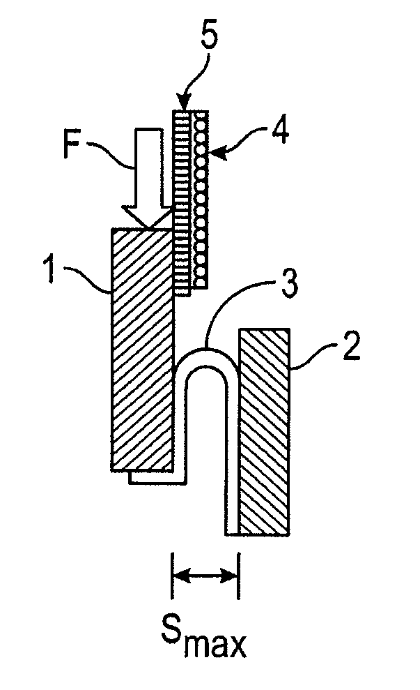
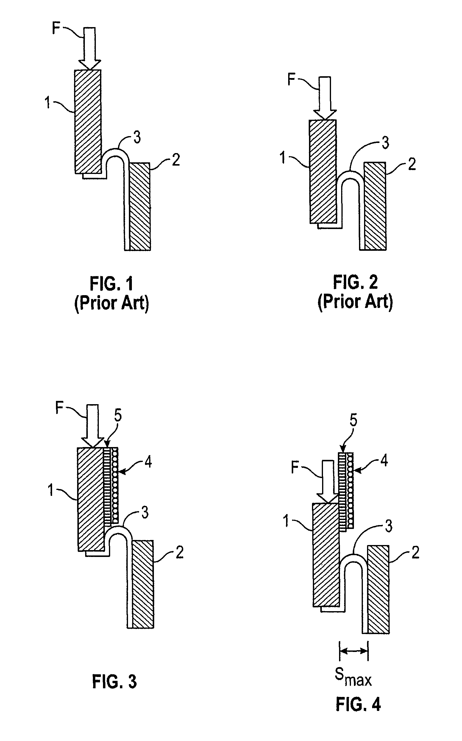
[0030]In the known energy absorption system shown in FIG. 1 there is in the normal condition of the substantially U-shaped respectively U-like bent material strip 3, the longer leg areally connected with the inner side of the fixed bearing 2. Following the bending, the shorter leg of the substantially U-shaped material strip 3 abuts at the inner side of the movable carriage 1 and is usually screwed to the lower side of the latter. If, due to the effect of a force F—for example during an ungentle landing or a crash—the movable carriage 1, as shown in FIG. 2 is pushed downwards a partial stripping respectively excoriation of the longer leg of the substantially U-shaped material strip 3 from the fixed bearing 2 occurs. The bending of the substantially U-shaped material strip 3 thereby moves downward together with the movable carriage 1 so that the leg of the substantially U-shaped material strip 3 being connected to the movable carriage 1 is extended. Hereby, the crash energy is receiv...


PUM


Abstract

The present invention relates to an energy absorption system. The energy absorption system comprises a movable carriage, a fixed bearing and a deformable material strip. The deformable material strip is at least areally connected to the fixed bearing. Between the movable carriage and the fixed bearing a gap is formed. The energy absorption system further comprises means, which are suited to vary the size of the gap between the movable carriage and the fixed bearing.

Description

CROSS-REFERENCE TO RELATED APPLICATIONS[0001]Pursuant to 35 U.S.C. 119(a), the instant application claims priority to prior German application number 10 2008 017 815.2, filed Apr. 8, 2008.BACKGROUND OF THE INVENTION[0002]The present invention relates to an energy absorption system, which is in particular suited for seats in helicopters, air planes and motor vehicles. The energy absorption system consists of a movable carriage, a fixed bearing and a deformable material strip, wherein the deformable material strip is at least areally connected to the fixed bearing. The energy absorption system may be adjusted to a weight range being suited for the passenger.[0003]It is a commonly known problem, that during the transport of persons shocks may occur, which have to be absorbed in order that the person does not suffer any harm. In this regard it is necessary to transform the shock energy, such that the remaining impact onto the person is as low as possible. One possibility is the use of s...

Claims


Application Information

Patent Timeline
Patent Type & Authority Patents(United States)
IPC IPC(8): F16F7/12
CPCB60N2/24B60N2/4242B60N2/42736B60N2/42781F16F7/123
Inventor BAUER, ROLAND
Owner B E AEROSPACE FISCHER
Why Eureka
Try Eureka