Light emitting device

a light-emitting device and light-emitting technology, which is applied in the direction of semiconductor devices, basic electric elements, electrical appliances, etc., can solve the problems of low concavity volume and variance in light distribution, so as to achieve light-emission efficiency and light distribution further enhanced, and the variation of light distribution can be kept to a minimum

Active Publication Date: 2013-10-08
NICHIA CORP
View PDF15 Cites 5 Cited by
  • Summary
  • Abstract
  • Description
  • Claims
  • Application Information

AI Technical Summary

Benefits of technology

[0007]In view of this, it is an object of the present invention to provide a light emitting device with which variance in light distribution can be kept to a minimum, while light-emission efficiency and light distribution can be further enhanced.
[0016]With the light emitting device according to one aspect of the present invention, variance in light distribution can be kept to a minimum, while light-emission efficiency and light distribution can be further enhanced.

Problems solved by technology

When the concavity is made shallower, however, this lowers the volume of the concavity, so when the translucent sealing resin is packed inside the concavity, if the amount of translucent sealing resin used varies from one light emitting device to the next, the surface of the light emitting element or the wires may be exposed from the translucent sealing resin, or the translucent sealing resin may overflow the concavity, creating a convex shape that sticks out on the light emitting face side.
Thus, a problem with light emitting devices was that the shape of the translucent sealing resin was not consistent, and this led to variance in the light distribution.

Method used


Image

  • Light emitting device
  • Light emitting device
  • Light emitting device

Examples


embodiment 1

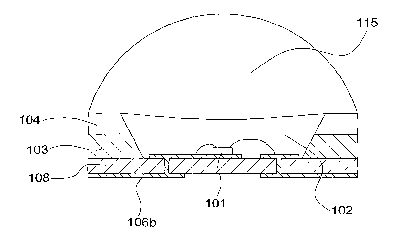
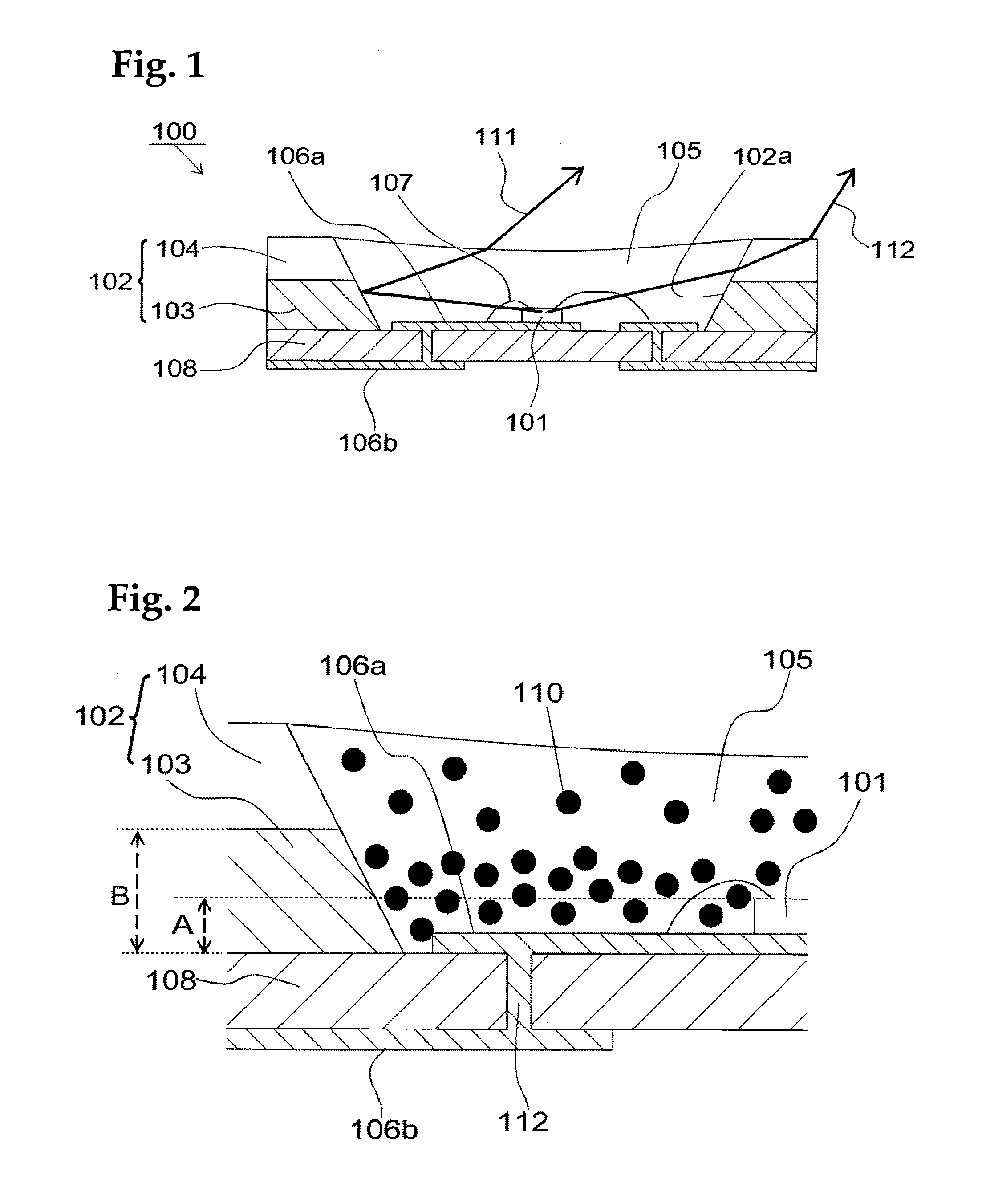
[0029]FIG. 1 is a simplified cross section of the light emitting device 100 of an embodiment of the present invention.

[0030]The light emitting device shown in FIG. 1 comprises at least a light emitting element 101 and a package 102 that can control the light distribution from the light emitting element 101.

Package 102

[0031]The package 102 contains the light emitting element 101, with the light emitting element 101 being accommodated in the interior, and comprises a concavity 102a that is filled from above with a translucent sealing resin 105. The side wall that form this concavity 102a of the package 102 comprise a light reflector 103 that reflects light from the light emitting element 101, and a light transmitter 104 that transmits light from the light emitting element to the outside.

[0032]The light reflector 103 and the light transmitter 104 do not necessarily have to be formed integrally, but they are preferably included integrally in the package. The phrase “included integrally”...

embodiment 2

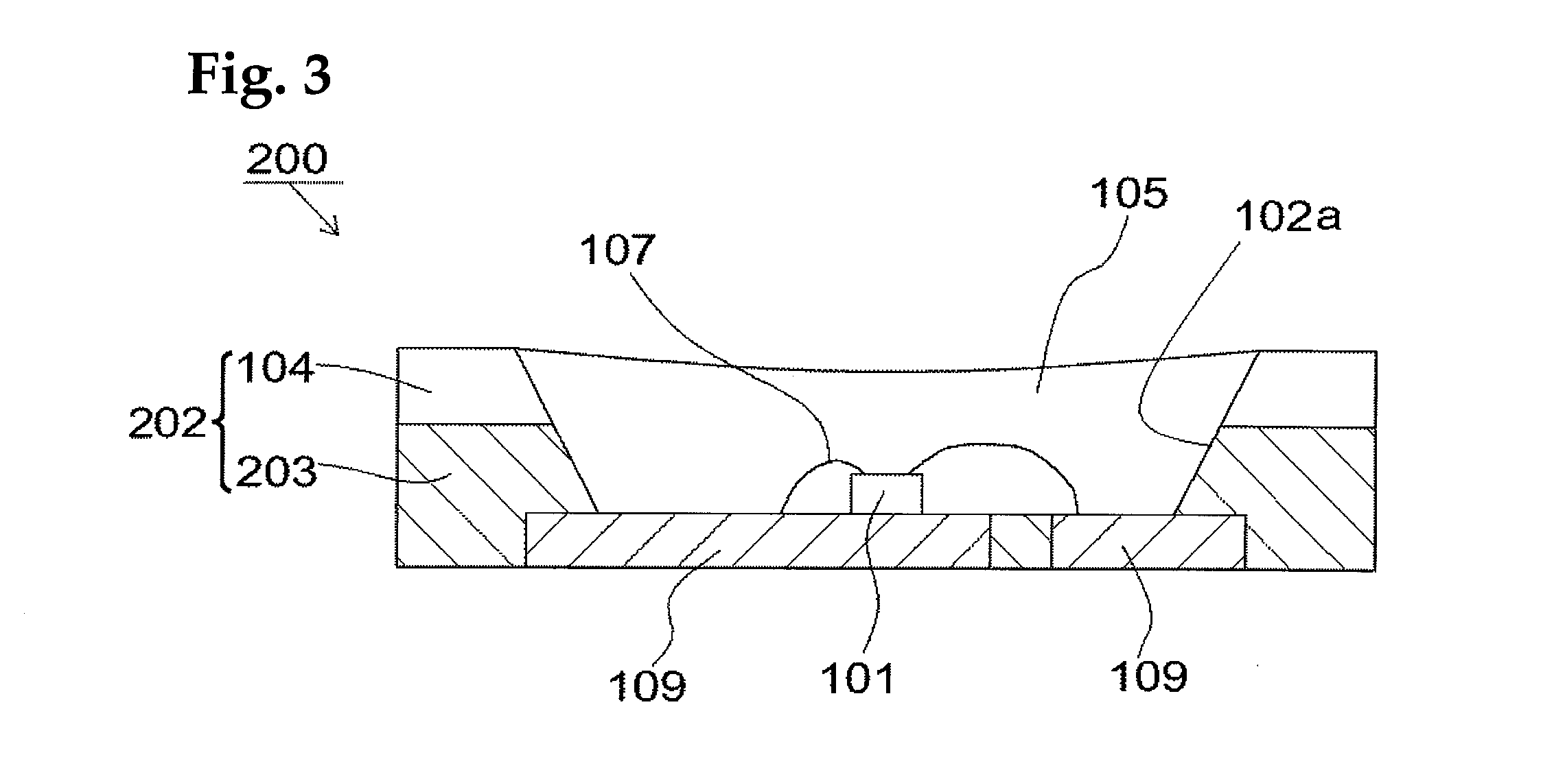
[0077]FIG. 3 is a simplified cross section of the light emitting device pertaining to Embodiment 2. Embodiment 2 is substantially the same as Embodiment 1, except that no substrate is used, and instead the light emitting element 101 is placed on a lead frame 109, and the concavity 102a is formed by a package 202 on part of the lead frame 109 so as to surround this light emitting element 101.

[0078]A light emitting device with excellent heat diffusion can be obtained by using the lead frame 109 as a conductive member. The lead frame 109 is embedded in a light reflector 203 of the package 202, and the top face of the lead frame 109 appears at the bottom face of the concavity 102a, which forms the package 202 in which the light reflector 203 and / or the light transmitter 104 are formed integrally.

Lead Frame 109

[0079]The lead frame 109 may be substantially in the form of a board, but may be in the form of a board that undulates or a board that has bumps. The thickness thereof may be unifo...

embodiment 3

[0081]Embodiment 3 is substantially the same as Embodiment 1, except that the lead frame 109 is used, a light reflector 303 is injection molded, the light transmitter 104 is placed on the light reflector 303, and the result is a frame insert type of light emitting device 300 comprising a package 302.

[0082]FIG. 4a is a cross section of the light emitting device 300 in Embodiment 3, FIG. 4b is an oblique view of the device from the outside, and FIG. 4c is a view from the light emitting face side. In FIGS. 4b and 4c, the translucent sealing resin is not shown, and the hatched parts show the places where the light reflector 303 is provided.

[0083]As shown in FIGS. 4a and 4b, the lead frame 109 sticks out to the outside from the light reflector 303, and is bent and disposed on the bottom face (the face that serves as the mounting face) and the side faces of the light emitting device 300. Consequently, a side face-emission (a so-called side view) type of light emitting device can be obtain...


PUM


Abstract

A light emitting device, which has: a light emitting element; a package that comprises a concavity for holding the light emitting element, and that has on its side wall where the concavity is integrally formed a light reflector for reflecting light from the light emitting element and a light transmitter for transmitting light from the light emitting element to the outside.

Description

CROSS-REFERENCE TO RELATED APPLICATIONS[0001]This national phase application claims priority to Japanese Patent Application No. 2009-147353 filed on Jun. 22, 2009. The entire disclosure of Japanese Patent Application No. 2009-147353 is hereby incorporated herein by reference.TECHNICAL FIELD[0002]This invention relates to a light emitting device, and more particularly to a surface-mount type of light emitting device used in lighting fixtures, displays, portable telephone backlights, auxiliary light sources for moving picture illumination, and other general, consumer-use light sources.BACKGROUND ART[0003]A light emitting device with a light emitting diode (LED) or other such light emitting element generally is compact, has good power efficiency, and emits light in vivid colors. Also, since this light emitting element is a semiconductor element, there is no worry about bulb breakage or the like. Furthermore, it has excellent initial drive characteristics, and withstands repeated switch...

Claims


Application Information

Patent Timeline
Patent Type & Authority Patents(United States)
IPC IPC(8): H01L33/50H01L33/58
CPCH01L33/58H01L33/60H01L24/97H01L33/486H01L2224/48091H01L2224/48227H01L2924/00014H01L2224/48247H01L2924/12041H01L2924/00H01L2924/181H01L2924/12035H01L2924/12042H01L2224/48237H01L2224/48257H01L2924/00012
Inventor TAKINE, KENJI
Owner NICHIA CORP
Why Eureka
Try Eureka