Small diameter radiation sensor cable

a radiation sensor and small diameter technology, applied in the field of very small diameter radiation sensor cables, can solve the problems of high cost, high manufacturing cost, and inability to meet the needs of small diameter optical fibers, and achieve the effects of low cost, good strength and fit, and high clarity

Active Publication Date: 2012-11-08
ANGIODYNAMICS INC
View PDF7 Cites 4 Cited by
  • Summary
  • Abstract
  • Description
  • Claims
  • Application Information

AI Technical Summary

Benefits of technology

[0030]Alternatively or in addition thereto, an exterior coating of heat shrinkable material can be added thereto for good strength and fit. The shrink tubing covers at least the detector end of the device and protects the detector, while keeping the components together in a tight bundle that remains flexible and can move in all directions. Where the cap is opaque, part of the cap can protrude from the heat shrinkable tubing. The shrink tubing can also cover most or all of the cable, but this will generally not be needed since plastic optical fibers are usually already jacketed, although the heat shrinkable tubing will also function to keep the fibers tightly bundled and thus may be of benefit.
[0031]Suitable plastics for the blind cap include high impact polystyrene, polybutadiene, acrylonitrile butadiene styrene, polyvinyl chloride, polycarbonate, polyacrylate, polyethylene terephthalate glycol, high density polyethylene, polypropylene, high impact rigid polyvinyl chloride, and polytetrafluoroethylene, and blends and copolymers thereof. Preferred materials are opaque in color to keep the assembly light tight. Alternatively, the cap can be covered in an opaque material and thus plastics with high clarity can be used, such as polycarbonate and polyacrylate.

Problems solved by technology

Manufacturing a high volume of such sensor cables is difficult because an accurate and repeatable connection of the plastic scintillator fiber to the plastic optical fiber is required.
The problem arises from working with small diameter optical fibers that must be constructed accurately, yet at a low cost.
The current process used to create a sensor cable with a plastic scintillation detector relies on many precise, time-consuming steps.
These cuts and polishes are difficult to do because the diameter (1 mm) and length (2 mm) of the scintillation fiber are very small.
This step is challenging due to the small size of the fibers and the need to perfectly align their cores.
The finished assembly is vulnerable to breakage because reliance is placed on the strength of the epoxy bond to hold the assembly together, and on a soft jacket material (PE or PVC) to hold the assembly in alignment.
Due to the labor intensive process and time consuming steps, it is very expensive to produce a detector in this fashion, and the process also introduces variability from detector to detector.
Applying these connectors adds more time to the process, and the FC and SMA connectors are expensive.

Method used


Image

  • Small diameter radiation sensor cable
  • Small diameter radiation sensor cable
  • Small diameter radiation sensor cable

Examples


Embodiment Construction

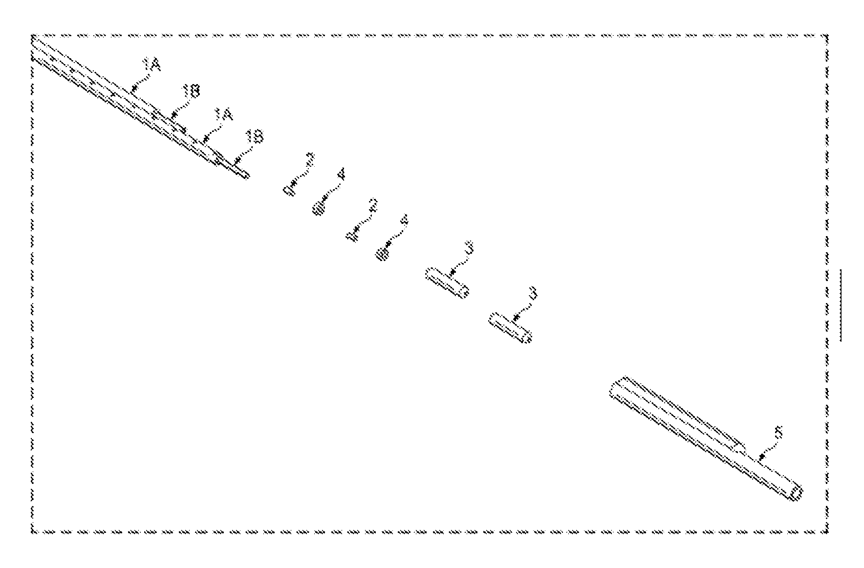
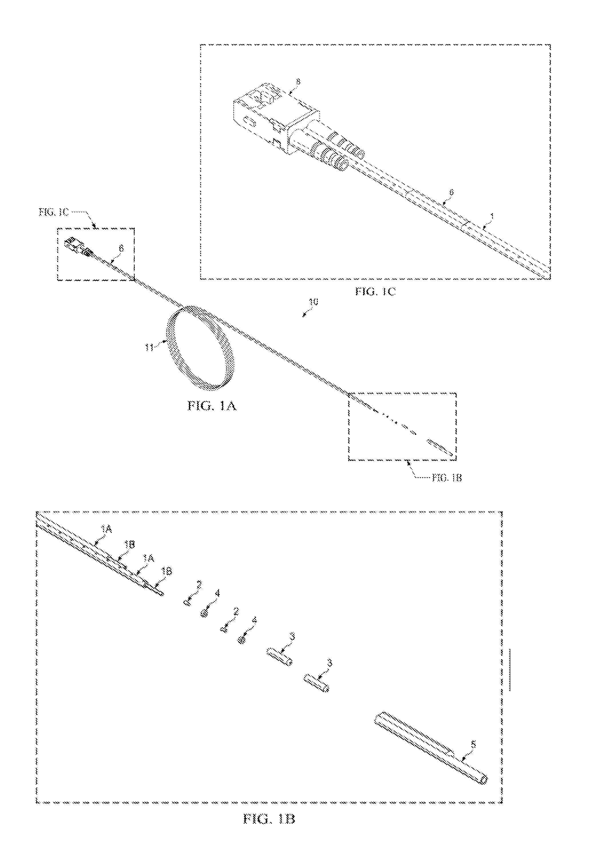
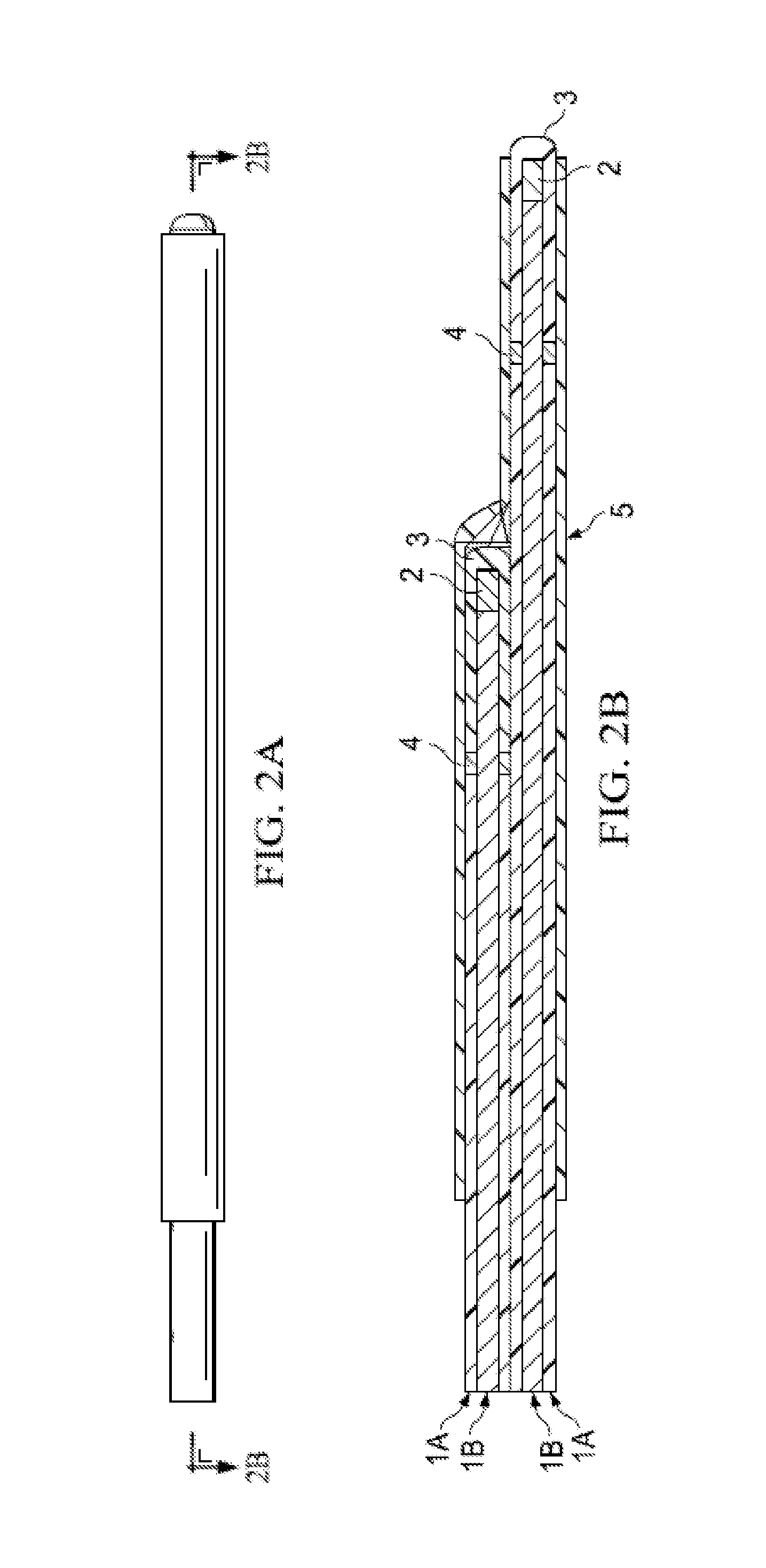
[0054]The parts of FIG. 1A-C are listed herein and preferred materials provided:

PartNo.DescriptionPreferred materials1Optical fiberMITSUBISHI SUPER ESKA 1 MMDUPLEX PLASTIC OPTICAL FIBERSH40022Scintillating fiberBCF-60 SAINT GOBAINSCINTILLATING FIBER PEAKEMMISSION 530 NM3fiber capHIGH IMPACT POLYSTYRENE4AdhesiveEPOXY TECHNOLOGIES EPO-TEK 3015Heat shrinkableRAYCHEM THERMOFIT CGPE-105tubingHEAT-SHRINKABLE TUBING6Lot Code LabelNA8AdaptorSCRJ CONNECTOR11Coiled section of cable.NAProtruding ends allowsfor calibration of eachcable and is apreferred packagingmethod.

[0055]Turning to FIG. 1, the duplex scintillation detector cable 10 has a first and second optical fibers 1. The jacket or covering 1A has been stripped or removed from the portion of the first optical fiber 1 adjacent to the distal ends of each fiber (see also FIG. 2B), leaving a portion of each optical fiber 1B exposed. First and second scintillating fibers 2 are shown, along with drop of adhesive 4 and fiber cap 3. The length ...


PUM

PropertyMeasurementUnit
diameteraaaaaaaaaa
diameteraaaaaaaaaa
diameteraaaaaaaaaa

Abstract

A duplex plastic optical fiber may be used to create a dual detector system, which allows for the detection of two distinct areas of radiation in a single sensor cable device. A fiber cap holds a scintillating fiber and slides over an exposed portion of an optical fiber adjacent to an end of the optical fiber to create a concentric connection for a radiation sensor cable used in medical radiation therapy.

Description

CROSS-REFERENCE TO RELATED APPLICATIONS[0001]This application claims priority to 61 / 481,503, filed May 2, 2011, and incorporated by reference in its entirety.STATEMENT REGARDING FEDERALLY SPONSORED RESEARCH OR DEVELOPMENT[0002]N / ANAMES OF PARTIES TO A JOINT RESEARCH AGREEMENT[0003]N / AREFERENCE TO AN APPENDIX SUBMITTED ON COMPACT DISC[0004]N / AFIELD OF THE INVENTION[0005]This invention relates to radiation sensor cables of very small diameter, such that they are suitable for use in medical applications.BACKGROUND OF THE INVENTION[0006]A scintillator is a special material that exhibits scintillation—the property of luminescence when excited by ionizing radiation. Luminescent materials, when struck by an incoming particle, absorb its energy and scintillate, in other words they reemit the absorbed energy in the form of light.[0007]A scintillation detector or scintillation counter is obtained when a scintillator is coupled to a light sensor such as a photomultiplier tube (PMT), photodiode...

Claims


Application Information

Patent Timeline
Patent Type & Authority Applications(United States)
IPC IPC(8): G01T1/20B29C65/72B29C65/52G02B6/00
CPCG01T1/201B32B2551/00B32B2535/00B32B2307/40Y10T156/1062B32B38/0036B32B38/0004B32B37/142G02B6/4486B32B2305/10
Inventor LEPKE, STEVENHYMAN, ERICISHAM, JOHNDAHL, RANDY
Owner ANGIODYNAMICS INC
Why Eureka
Try Eureka