
Method for joining a pair of electric cables

a technology of electric cables and connecting elements, which is applied in the manufacture of cables/conductor parts, basic electric elements, electrical equipment, etc., can solve the problems of unfavorable lubricating material reduction, and precise and uniform control of the ejection speed of the supporting element. , to achieve the effect of reducing the amount of lubricating material, promoting the ejection speed of the supporting element, and reducing the amount of lub

Active Publication Date: 2013-10-15
PRYSMIAN CAVI E SISTEMI ENERGIA
View PDF20 Cites 4 Cited by
  • Summary
  • Abstract
  • Description
  • Claims
  • Application Information

AI Technical Summary

Benefits of technology

[0031]Therefore, in one aspect, the present invention relates to a method of splicing at least one pair of cables, each cable including at least one conductor, said method comprising the steps of: setting a elastic tubular sleeve supported in a radially expanded condition on at least one supporting element; disposing the sleeve, in engagement with said supporting element, in a substantially coaxial position around one of said cables; connecting each conductor of said at least one pair of cables to obtain a splicing region between these cables; positioning the sleeve in engagement with the supporting element around the splicing region; axially moving the supporting element relative to the tubular sleeve, so as to cause a radial elastic shrinkage of the tubular sleeve capable of inducing an axial ejection thrust on the supporting element itself; counteracting the axial ejection thrust induced by the elastic shrinkage of the tubular sleeve; and adjusting the axial movement speed of the supporting element so as to adapt it to the elastic shrinkage speed of the tubular sleeve.
[0033]In addition, the method of the present invention is particularly advantageous because it is not affected by the environmental temperature present at the moment of the installation. In fact, an important lowering of the environmental temperature (above all when said temperature goes down under about 10° C.) causes a reduction often of great amount, in the shrinkage speed of the tubular sleeve relative to the ejection speed of the support, this fact involving a greater risk as regards formation of the above mentioned air pockets.
[0034]Furthermore, the method in accordance with the present invention enables the risks of jamming or locking of the supporting element during axial sliding of the latter to be avoided or at least greatly reduced, above all in the starting ejection step, in the absence of axial forces imposing a correct sliding to the supporting element within the elastic tubular sleeve. In fact, since the method of the present invention allows a precise and uniform control of the ejection speed of the supporting element, a possible jamming during the elastic shrinkage step of the tubular sleeve is advantageously averted.
[0035]In addition, by the method of the present invention use of lubricating materials that are usually placed at the interface between the elastic tubular sleeve and the supporting element to promote ejection of said supporting element is reduced. As above said, said lubricating materials can give rise to contact irregularities at the sleeve / spliced cables interface and / or promote entrapping of air particles between the inner surface of the elastic sleeve and the underlying cables. Furthermore, where the sleeves are submitted to long storage periods, said lubricating materials can gradually escape from the sleeve and / or be submitted to qualitative decay and, as a result, to a partial loss of their lubricating function. Since the method of the present invention allows the ejection speed of the supporting element to be adjusted so as to adapt it to the elastic shrinkage speed of the tubular sleeve, the amount of lubricating material can be advantageously reduced as compared with the self-ejecting systems of the known art. In fact, in a self-ejecting system use of a rather high amount of lubricating material is convenient, which material is interposed between the supporting element and the tubular sleeve, for the purpose of ensuring a full implementation of said ejection. In compliance with the present invention, on the contrary, it is sufficient to ensure the only amount of lubricating material that is strictly indispensable to avoid friction between the supporting element and the sleeve being so strong that the sleeve itself is deteriorated, as the ejection action does not rely on the lubricating material but on the axial movement of the supporting element relative to the sleeve, which movement is directly controlled from the outside.
[0036]The method of the present invention enables the above mentioned drawbacks to be overcome due to adjustment of the ejection speed of the supporting element relative to the shrinkage speed of the sleeve on the underlying spliced cables. In particular, the method of the present invention comprises the step of driving ejection of the supporting element by application of a pulling force oriented in an axial direction and applied to at least one end of the supporting element projecting externally of the elastic tubular sleeve. In this way, the method of the present invention enables a correct ejection of the supporting element to be ensured in a substantial absence of jamming actions both in the starting ejection step and during separation from the elastic tubular sleeve, which jamming actions are caused by friction generated by the sleeve elastically expanded on the supporting element.

Problems solved by technology

The Applicant has perceived that the above mentioned formation of undesired air bubbles generally takes place when ejection of the supporting element does not gradually follow shrinkage of the elastic tubular sleeve, which event can cause an uneven shrinkage of the sleeve itself.

Method used


Image

  • Method for joining a pair of electric cables
  • Method for joining a pair of electric cables
  • Method for joining a pair of electric cables

Examples


Embodiment Construction

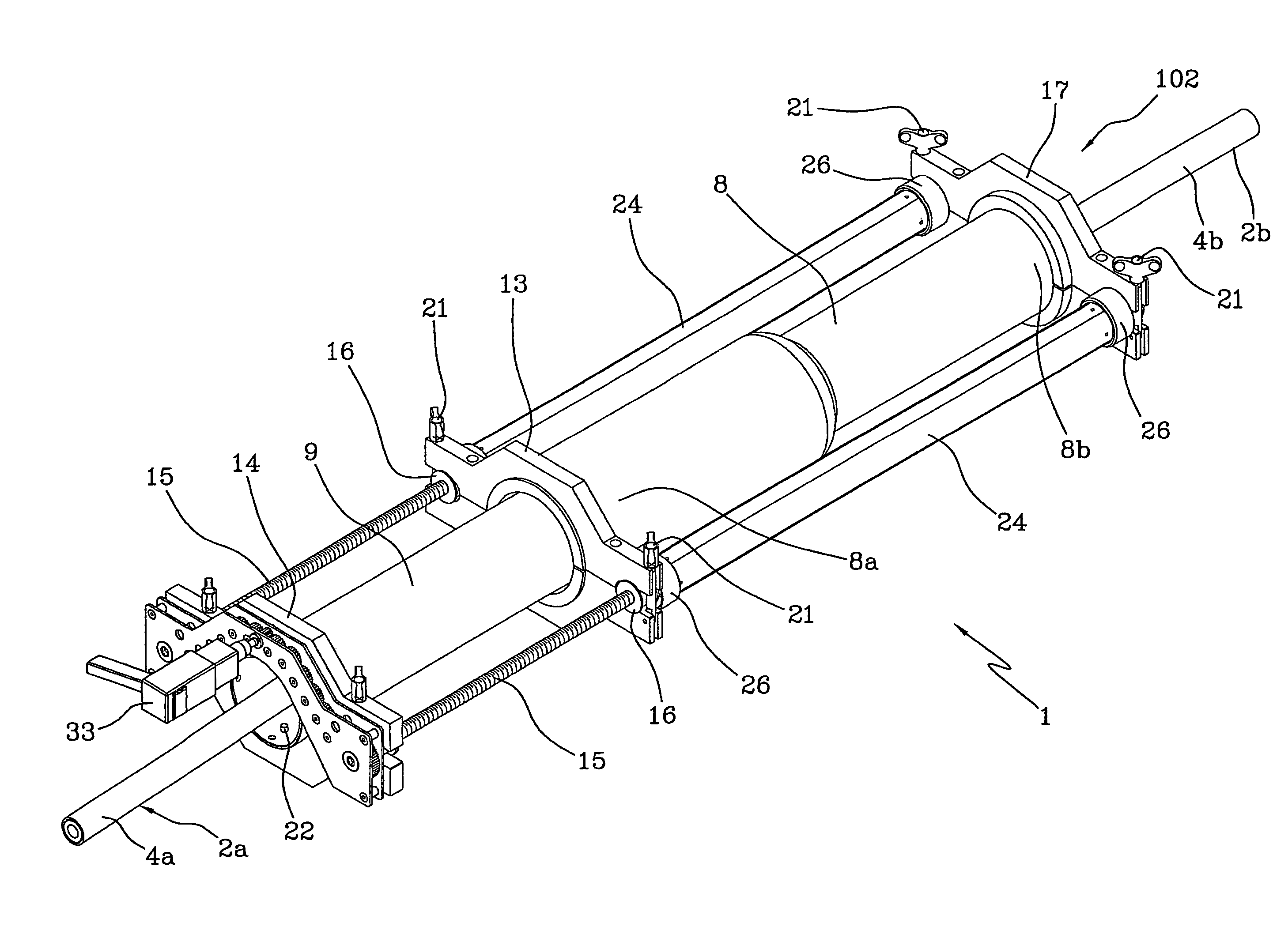
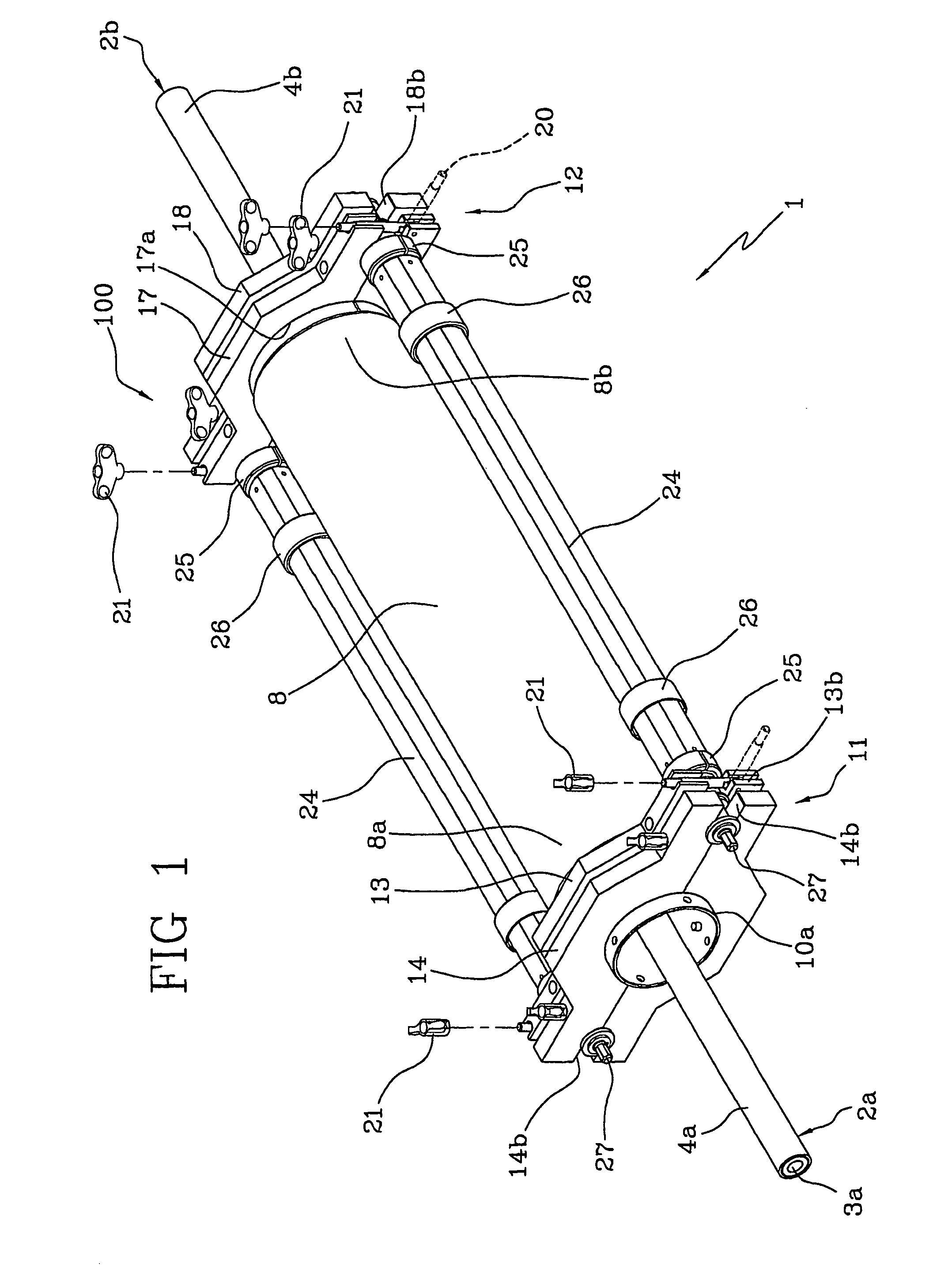
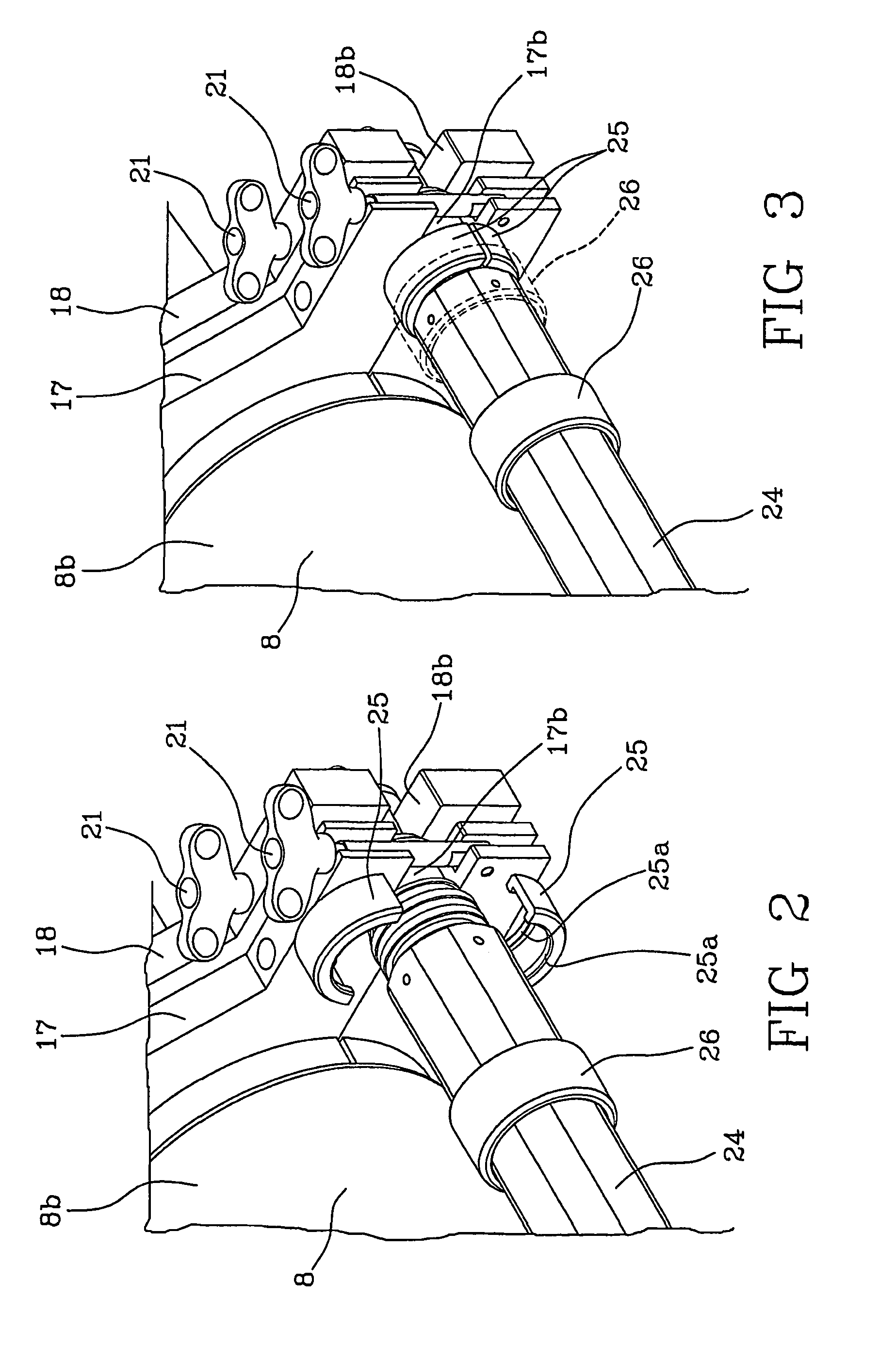
[0048]With reference to the drawings, an apparatus to splice at least one pair of cables in accordance with the present invention has been generally identified by reference numeral 1.

[0049]In the course of the present description and in the accompanying drawings, reference will be made by way of example to the splicing between two electric high-voltage cables 2a, 2b. It is however to be pointed out that the invention can be also applied to electric connections being part of an electric and / or telecommunications network, as well as to any electric connection between one cable and one terminal of an electric apparatus.

[0050]In addition, the constituent elements of the splicing between cables 2a, 2b will not be described in detail because they can be made in a conventional manner known by itself.

[0051]Apparatus 1 lends itself to be used in creating a splicing between at least one pair of cables 2a, 2b each comprising at least one conductor 3a, 3b externally coated with a polymer sheath...


PUM

PropertyMeasurementUnit
voltageaaaaaaaaaa
voltageaaaaaaaaaa
voltageaaaaaaaaaa

Abstract

A method of splicing first and second cables may include providing an elastic tubular sleeve, supported by at least one supporting element, in a radially expanded condition; arranging the sleeve in the radially expanded condition around one cable; connecting the cables to obtain a splicing region; positioning the sleeve in the radially expanded condition around the splicing region; axially moving the at least one supporting element relative to the sleeve to cause radial elastic shrinkage of the sleeve capable of inducing axial ejection thrust on the at least one supporting element; counteracting the axial ejection thrust; and adjusting axial movement speed of the at least one supporting element to adapt the axial movement speed to a speed of the elastic shrinkage. Counteracting the axial ejection thrust may include applying axial reaction force to one end of the at least one supporting element axially projecting from the sleeve.

Description

CROSS-REFERENCE TO RELATED APPLICATIONS[0001]This application is a national stage entry from International Application No. PCT / IT2005 / 000609, filed on Oct. 19, 2005, in the Receiving Office of the Italian Patent and Trademark Office, the entire contents of which are incorporated herein by reference.FIELD OF THE INVENTION[0002]The present invention relates to a method for providing a splicing region between two electric cables for energy transport or distribution. More particularly, the present invention is concerned with a method for providing a splicing region between two electric cables for transport or distribution of high or ultra high-voltage energy.[0003]The present invention also pertains to an apparatus for providing said splicing region.[0004]In the present specification the term “medium voltage” is used with reference to a voltage typically included between about 1 kV and about 30 kV, while the term “high voltage” refers to a voltage higher than 30 kV. The term “ultra high...

Claims


Application Information

Patent Timeline
Patent Type & Authority Patents(United States)
IPC IPC(8): H01R43/00
CPCH02G1/14H02G15/1826H01B13/22Y10T29/53243Y10T29/49195Y10T29/49202Y10T29/49194Y10T29/532
Inventor PORTAS, FRANCESCOVALLAURI, UBALDO
Owner PRYSMIAN CAVI E SISTEMI ENERGIA
Learn More