Switch having a plunger, a support terminal, and a coil spring

a technology of plunger and coil spring, which is applied in the direction of snap-action arrangement, contact surface shape/structure, contact, etc., can solve the problems of design work becoming complicated in order and the inability to obtain low-profile switches, and achieve the effect of small variation in operating characteristics and improved assembly accuracy

Active Publication Date: 2013-10-15
ORMON CORP
View PDF8 Cites 2 Cited by
  • Summary
  • Abstract
  • Description
  • Claims
  • Application Information

AI Technical Summary

Benefits of technology

[0009]One or more embodiments of the present invention provide a good-manipulation-feeling, low-profile switch in which the design work is simplified while the component lifetime is lengthened.
[0021]According to the present aspect, the position of the uprise piece in which the turning bracket of the support terminal is provided is controlled to improve assembly accuracy, and advantageously the switch having a small variation in operating characteristic is obtained.

Problems solved by technology

Therefore, the low-profile switch is not obtained.
Therefore, a contact pressure is deviated by a minute inclination generated in the plunger 40, and design work becomes complicated in order to secure a contact balance.

Method used


Image

  • Switch having a plunger, a support terminal, and a coil spring
  • Switch having a plunger, a support terminal, and a coil spring
  • Switch having a plunger, a support terminal, and a coil spring

Examples


first embodiment

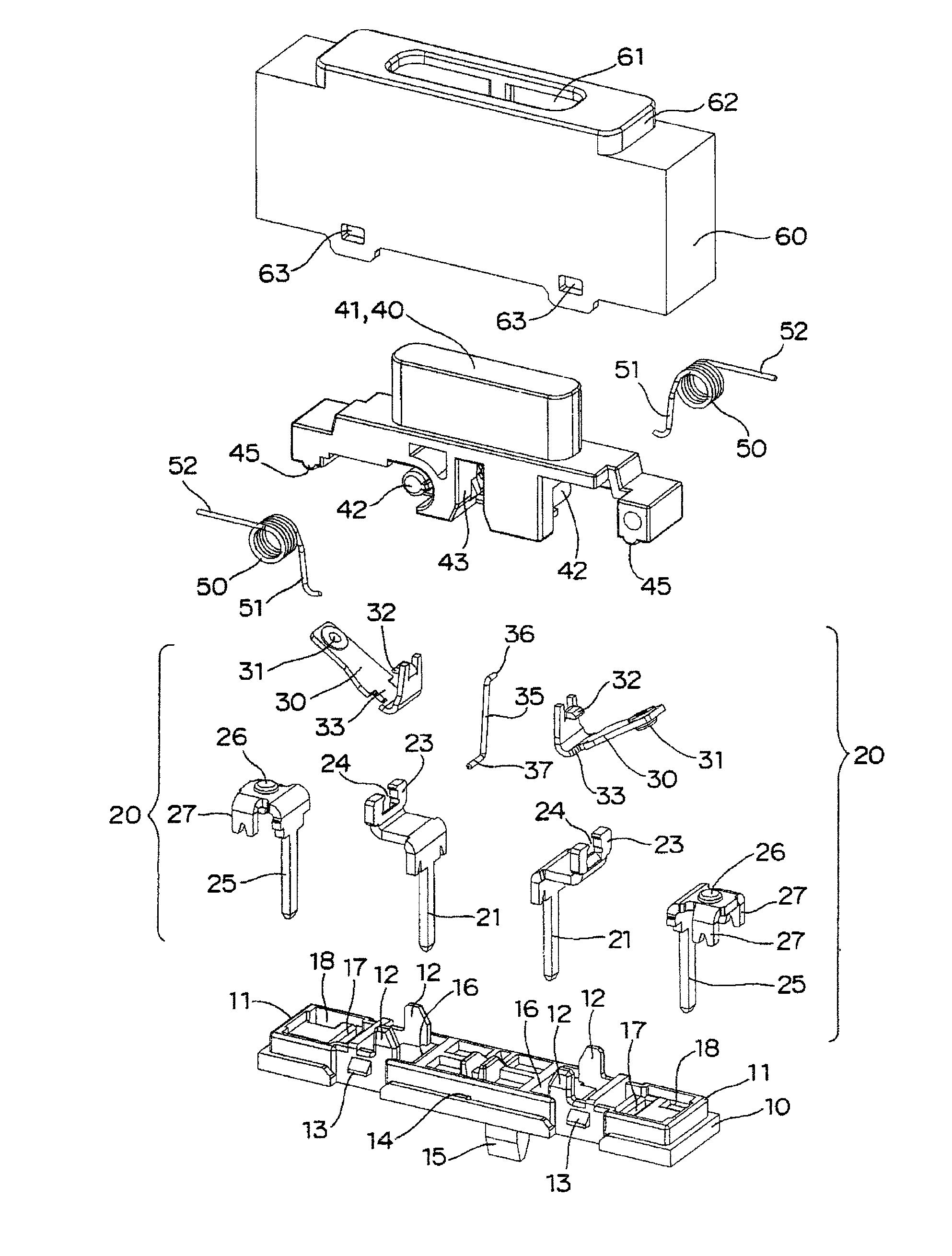
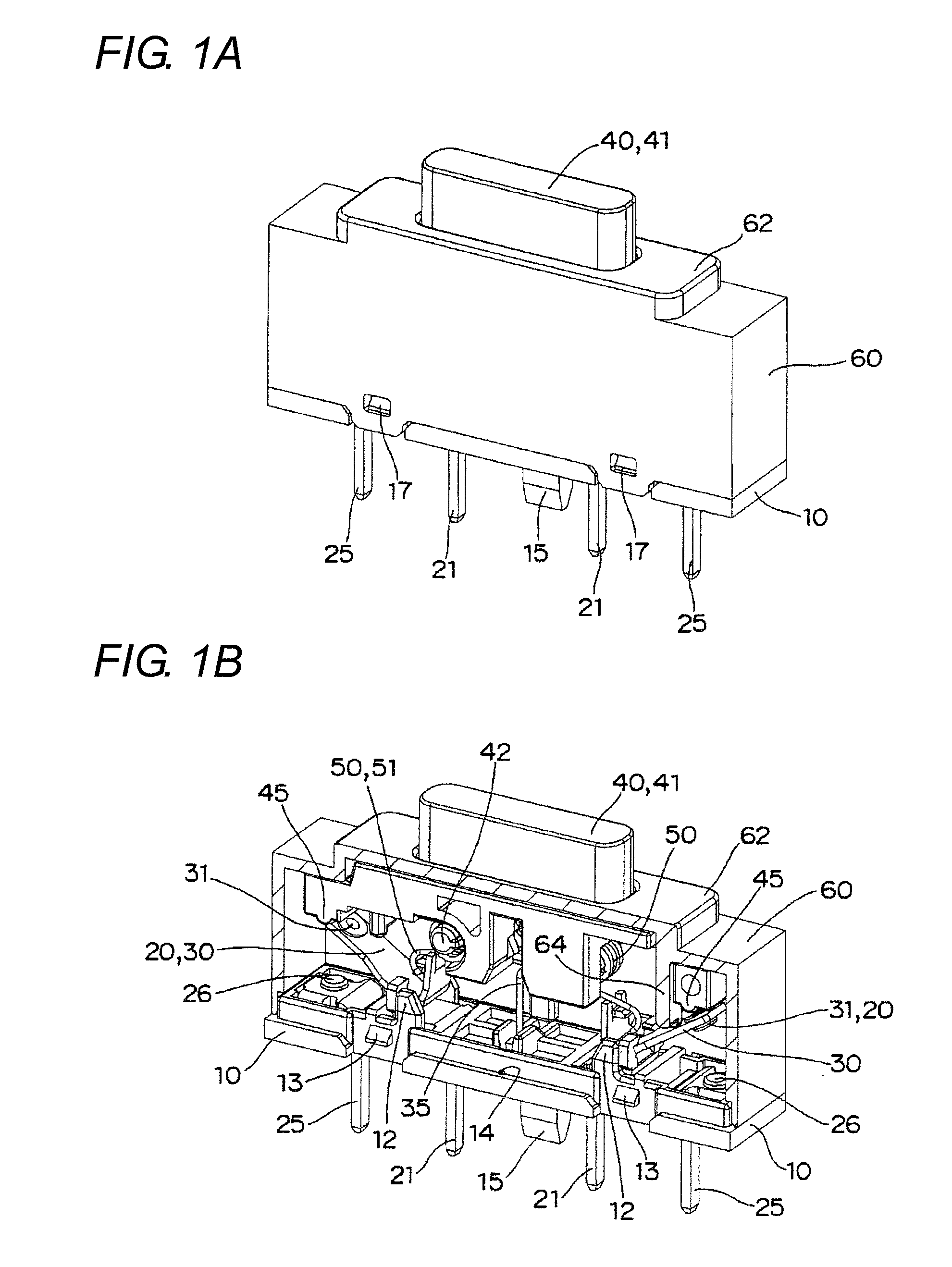
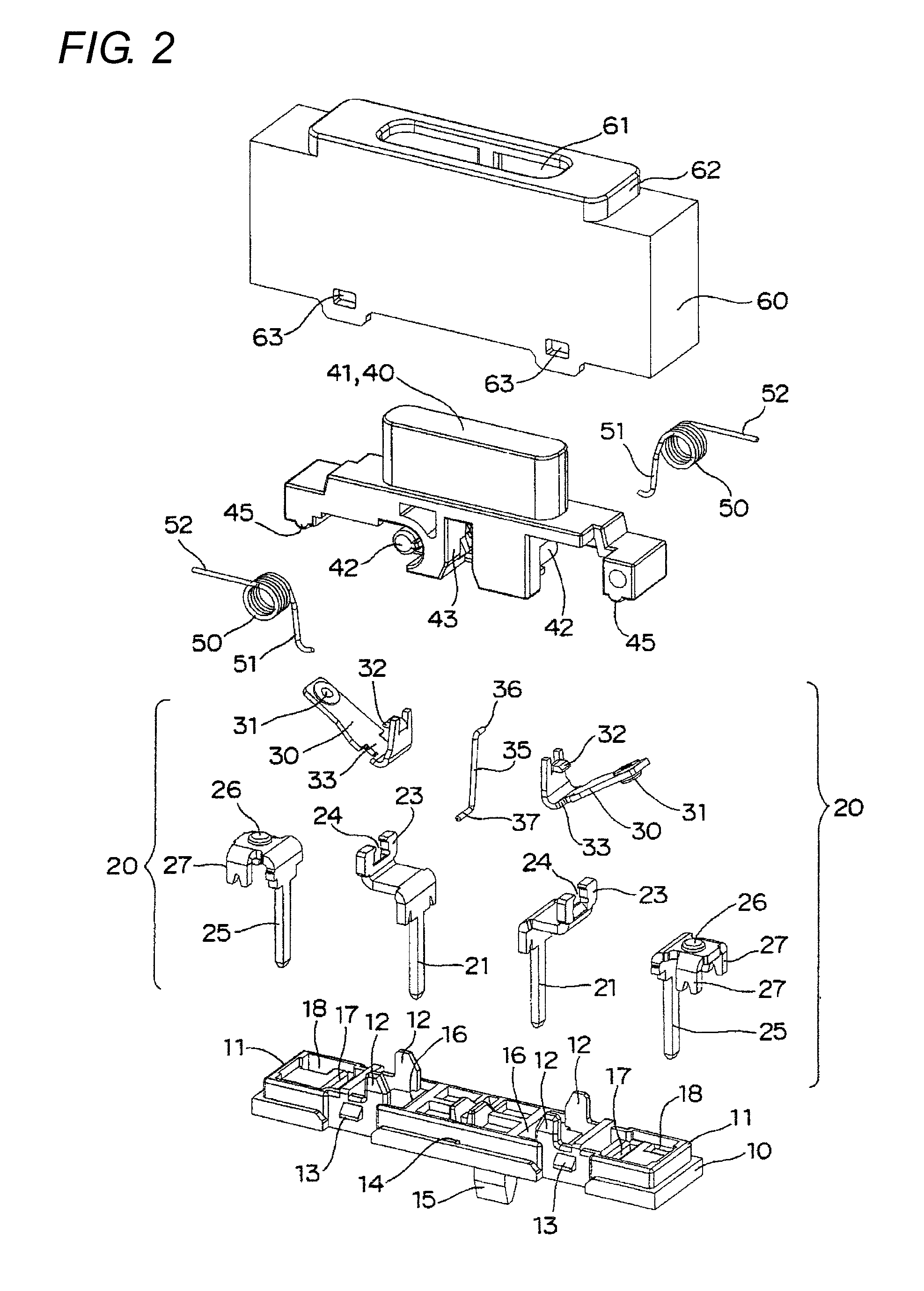
[0045]As illustrated in FIGS. 1 to 11, a switch according to the invention includes a base 10, two sets of contact mechanisms 20 and 20 assembled in the base 10, a pair of coil springs 50 and 50, a lock pin 35, a plunger 40 configured to manipulate the contact mechanisms 20 and 20, and a housing 60. The housing 60 is fitted in the base 10 to cover the contact mechanisms 20 and 20, and supports the plunger 40 while the plunger 40 is vertically movable.

[0046]As shown in FIG. 2, in the base 10, an annular rib 11 is projected along an upper surface of a peripheral edge portion, and two pairs of position controlling projections 12 are provided in an upper-end edge portion of the annular rib 11. Latching pawls 13 and 13 are projected from a side face of the annular rib 11, and a shaft hole 14 is made between the latching pawls 13 and 13. A latching pawl 15 is projected downward in an edge portion of a bottom surface of the base 10 in order to connect the base to a connector (not shown). I...

second embodiment

[0063]As shown in FIGS. 16 to 20, a method for manipulating the switch of the second embodiment will be described below.

[0064]As shown in FIG. 16A, the plunger 40 is biased upward by the spring force of the coil spring 50 before the manipulation. On the other hand, one end portion 51 of the coil spring 50 presses down the sliding tongue piece 32 of the moving contact piece 30. Therefore, one end portion of the moving contact piece 30 abuts on the lower end portion of the stopper 64 projected from the inner side face of the housing 60, and the position of the moving contact piece 30 is controlled, whereby the moving contact piece 30 does not drop off. At this point, the upper end portion 36 of the lock pin 35 is located in the initial region 44a of the cam groove 43 of the plunger 40.

[0065]When the manipulation portion 41 of the plunger 40 is pressed down, the coil spring 50 is bent, and one end portion 51 of the coil spring 50 biases the moving contact piece 30 in a direction in whi...

third embodiment

[0070] advantageously the assembling property is improved because the coil springs 50 and 50 can be assembled in the plunger 40 from the same direction.

[0071]In the switch according to one or more embodiments of the invention, the pressing projection 45 of the plunger 40 may be provided if needed, and the pressing projection 45 may be removed if not needed.

[0072]One or more embodiments of the present invention may be applied to not only the alternate type switch in which the lock pin is necessary, but also the momentary type switch the lock pin is not necessary.


PUM


Abstract

A switch has a base, a housing, a support terminal that is assembled in the base, a moving contact piece that is made of a band-shaped material having a section being formed into a substantial J-shape, a moving contact being provided in one end portion of the moving contact piece, an intermediate portion of the moving contact piece being turnably supported by a turning bracket of the support terminal, a plunger that is accommodated in an internal space while being vertically movable, wherein the internal space is formed by fitting the housing in the base, and a coil spring that is turnably supported by the plunger. The plunger is vertically moved such that one end portion of the coil spring is slid while brought into press-contact with an edge of the other end portion of the moving contact piece, whereby the moving contact piece is inverted to bring and separate the moving contact into contact with and from a fixed contact. The pair of moving contact pieces is disposed on the base such that axis centers of the moving contact pieces are parallel to an axis center in a longitudinal direction of the base and such that the moving contact pieces are located on both sides in a central portion in the longitudinal direction of the base.

Description

BACKGROUND OF THE INVENTION[0001]1. Technical Field[0002]The present invention relates to a switch, particularly to a switch in which a contact can be opened and closed by a pressing manipulation.[0003]2. Related Art[0004]Conventionally, for example, Japanese Unexamined Patent Publication No. 2009-32646 discloses a switch in which a contact can be opened and closed by a pressing manipulation.[0005]In the switch disclosed in Japanese Unexamined Patent Publication No. 2009-32646, a plunger 40 is vertically moved such that one end portion 51 of a coil spring 50 is slid while brought into press-contact with an edge of the other end portion of a moving contact piece 30, whereby the moving contact piece 30 is inverted to bring and separate a moving contact 31 into contact with and from a fixed contact 26.[0006]However, in the switch, a distance between supporting points of the coil springs 50 and 50 is lengthened and horizontal components of force are located in a point-symmetric manner t...

Claims


Application Information

Patent Timeline
Patent Type & Authority Patents(United States)
IPC IPC(8): H01H13/30
CPCH01H13/30H01H1/22H01H5/14H01H13/562
Inventor KIYONO, YASUHIRONARUO, TOSHIHIRO
Owner ORMON CORP
Why Eureka
Try Eureka