Duplex outlet with current indicator

a dual-outlet, current indicator technology, applied in the direction of audible signalling system, coupling device connection, instruments, etc., can solve the problems of affecting the efficiency of electrical appliances, etc., to achieve the effect of reducing power consumption

Inactive Publication Date: 2013-10-15
NITZ STEVEN M
View PDF27 Cites 23 Cited by
  • Summary
  • Abstract
  • Description
  • Claims
  • Application Information

AI Technical Summary

Benefits of technology

[0010]In view of the foregoing references, the inventor recognized the aforementioned inherent problems and observed that there is a need for an electrical outlet which allows a user to determine whether the outlet is drawing power at any given point in time and to mitigate power consumption should such a draw be deemed extraneous. Thus, the object of the present invention is to solve the aforementioned disadvantages and provide for this need.

Problems solved by technology

Since electricity is invisible, many people have no idea how much power is being consumed by an individual load.
As such, it is very difficult to determine what devices to turn off or not use in an effort to conserve electricity.
Even if one can read the power consumption label on the device, it is very difficult for the average consumer to determine what it costs per minute or per hour to run such equipment due to relatively complicated formulas, and the variable power rates in effect in various communities.
Specifically, electrical loads commonly known as “parasitic loads” or “phantom electricity” consume power or draw current even when in an off or a de-energized state.
In fact, such “parasitic loads” are common in both home and work environments and contribute to an overall staggering amount of power consumed around the world today.
While these devices fulfill their respective, particular objectives, each of these references suffer from one (1) or more of the aforementioned disadvantages.
Furthermore, many such devices only include one indicator light for a plurality of connectors.
Also, many such devices do not provide a means to mitigate extraneous power consumption.

Method used


Image

  • Duplex outlet with current indicator
  • Duplex outlet with current indicator
  • Duplex outlet with current indicator

Examples


Embodiment Construction

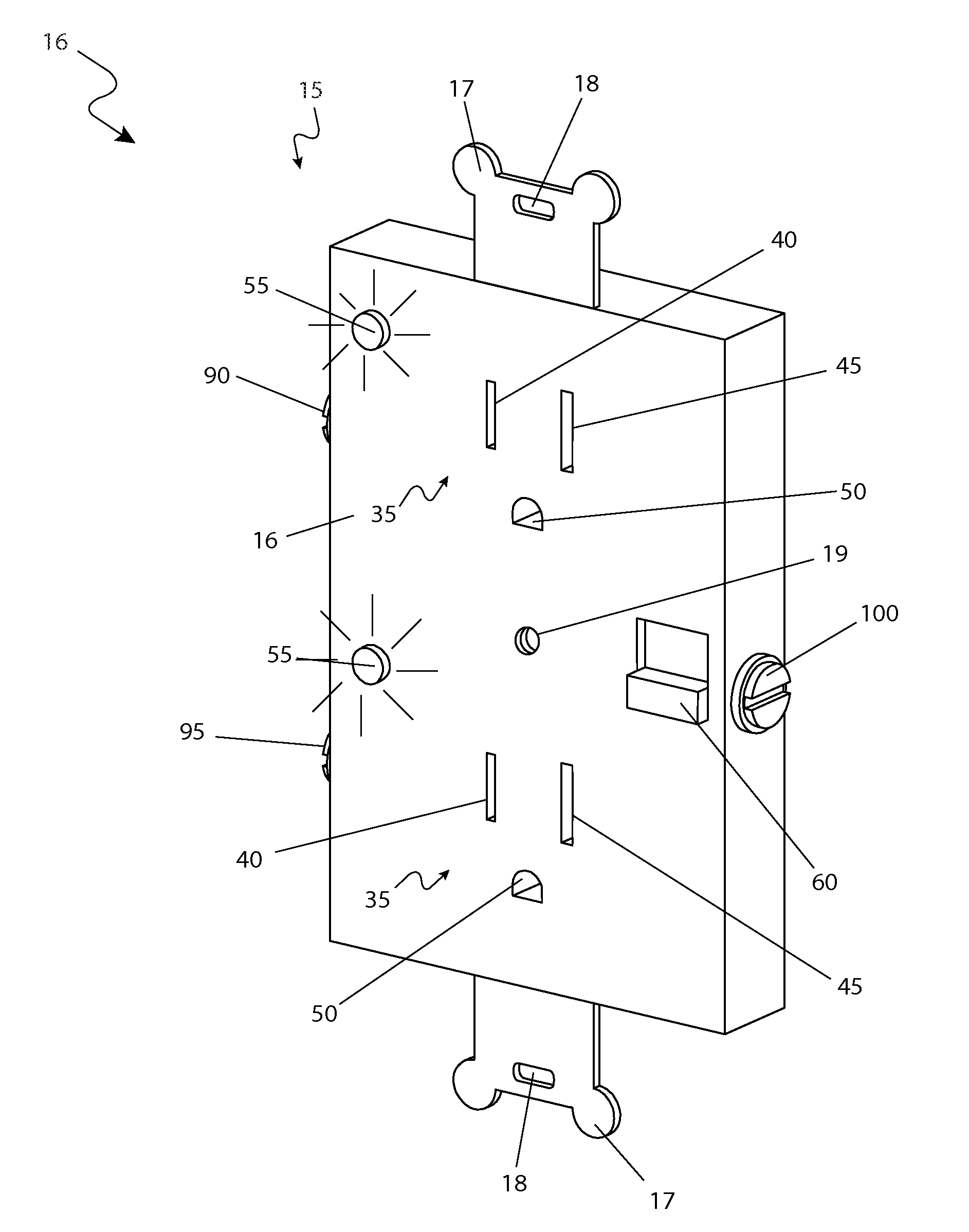
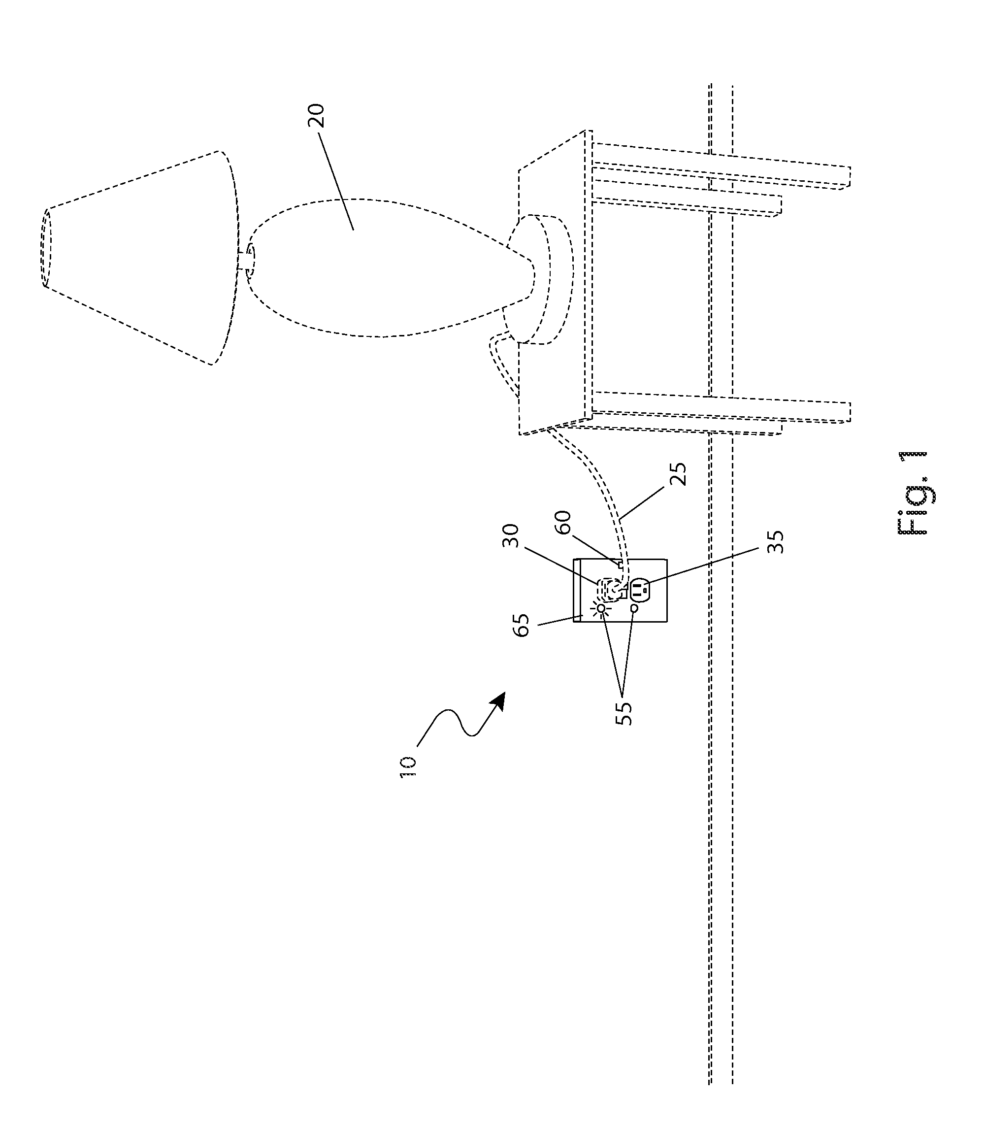
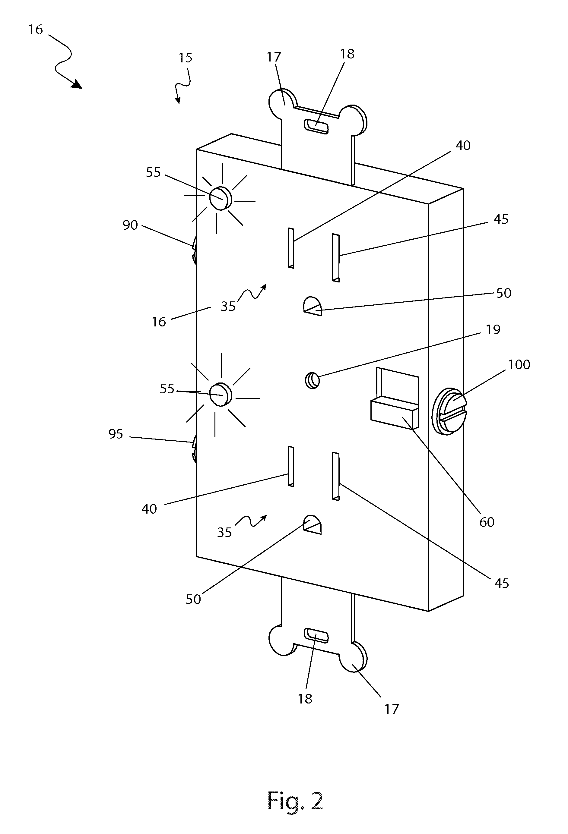
[0049]The best mode for carrying out the invention is presented in terms of its preferred embodiment, herein depicted within FIGS. 1 through 4. However, the invention is not limited to the described embodiment and a person skilled in the art will appreciate that many other embodiments of the invention are possible without deviating from the basic concept of the invention, and that any such work around will also fall under scope of this invention. It is envisioned that other styles and configurations of the present invention can be easily incorporated into the teachings of the present invention, and only one particular configuration shall be shown and described for purposes of clarity and disclosure and not by way of limitation of scope.

[0050]The terms “a” and “an” herein do not denote a limitation of quantity, but rather denote the presence of at least one of the referenced items.

[0051]The present invention describes a duplex outlet with current indicator (herein described as the “a...


PUM


Abstract

An apparatus that enables indication of power utilization from an electrical outlet to be visually provided to a user, comprising receptacles, an illumination means, and a toggle switch. When an electrical power cord is plugged into the apparatus and is drawing any amount of current above zero (0) amps, the illumination means will activate, thereby alerting the user that the device is drawing power, even if the device is turned off, and allowing the user to take corrective action if necessary. The integral toggle switch deactivates the power to the device while leaving it plugged in.

Description

RELATED APPLICATIONS[0001]The present invention was first described in and claims the benefit of U.S. Provisional Application No. 61 / 264,372 filed Nov. 25, 2009, the entire disclosures of which are incorporated herein by reference.FIELD OF THE INVENTION[0002]The present invention relates generally to electrical power outlets, and in particular, to a load sensor and indicator circuit for electrical power outlets.BACKGROUND OF THE INVENTION[0003]Electricity consumption continues to grow in our country. Not only are our homes becoming bigger which places larger demands on lighting and HVAC loads, but also the information and entertainment devices we put in them are becoming larger and more plentiful.[0004]Since electricity is invisible, many people have no idea how much power is being consumed by an individual load. As such, it is very difficult to determine what devices to turn off or not use in an effort to conserve electricity. Even if one can read the power consumption label on the...

Claims


Application Information

Patent Timeline
Patent Type & Authority Patents(United States)
IPC IPC(8): G08B21/00
CPCH02G3/18
Inventor NITZ, STEVEN M.
Owner NITZ STEVEN M
Why Eureka
Try Eureka