Driving methods for electrophoretic displays

a technology of electrophoretic display and driving method, which is applied in the direction of electric digital data processing, instruments, computing, etc., can solve the problems of particularly undesirable current method, and achieve the effect of preventing overdriving of electrophoretic display and highest speed

Active Publication Date: 2013-10-15
E INK CORPORATION
View PDF83 Cites 133 Cited by
  • Summary
  • Abstract
  • Description
  • Claims
  • Application Information

AI Technical Summary

Benefits of technology

[0017]The driving system and methods of the present invention enable interruption of updating images. The system and methods not only have the advantage that they can prevent overdriving of an electrophoretic display, but they also allow updating images in the highest speed possible. The overdriving phenomenon is usually caused by continuing applying a voltage to a medium even after the medium has reached the desired color state. As a result, overdriving often causes undesirable performance issues, for example, poor bistability.

Problems solved by technology

In light of this shortcoming, the current method is particularly undesirable in a situation where user interaction with an electronic device (such as an e-book) is an essential feature.

Method used


Image

  • Driving methods for electrophoretic displays
  • Driving methods for electrophoretic displays
  • Driving methods for electrophoretic displays

Examples


example 1

Pixel Counter Table

[0085]This example is shown in FIG. 7. The current image has pixels A and B in the black state and pixels C and D in the white state and the next image has pixels A and C in the white state and pixels B and D in the black state.

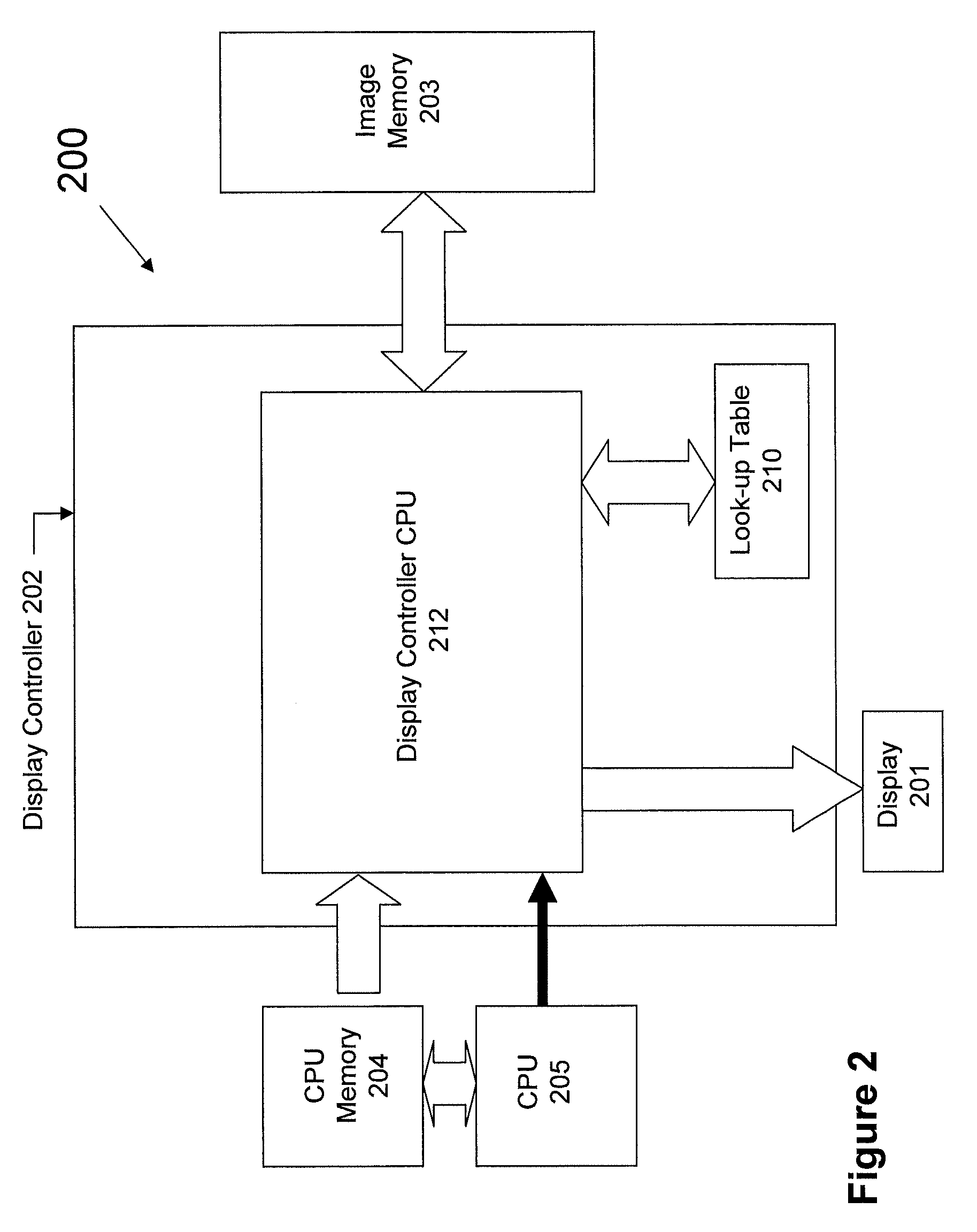
[0086]A display controller compares the current and next images and consults a look-up table based on the waveforms of FIG. 4. The driving data obtained from the look-up table are presented in the pixel counter table of FIG. 7.

[0087]The pixel counter table shows that while driving pixel A from black to white, a voltage of +V must be applied to the pixel for a period of ten frames, which is expressed in the table as “+10” and while driving pixel D from white to black, a voltage of −V must be applied to the pixel for a period of ten frames, which is expressed in the table as “−10”.

[0088]For pixels B and C, since no color change occurs between the current image and the next image, no driving voltage is applied to these two pixels during the up...

examples 2-4

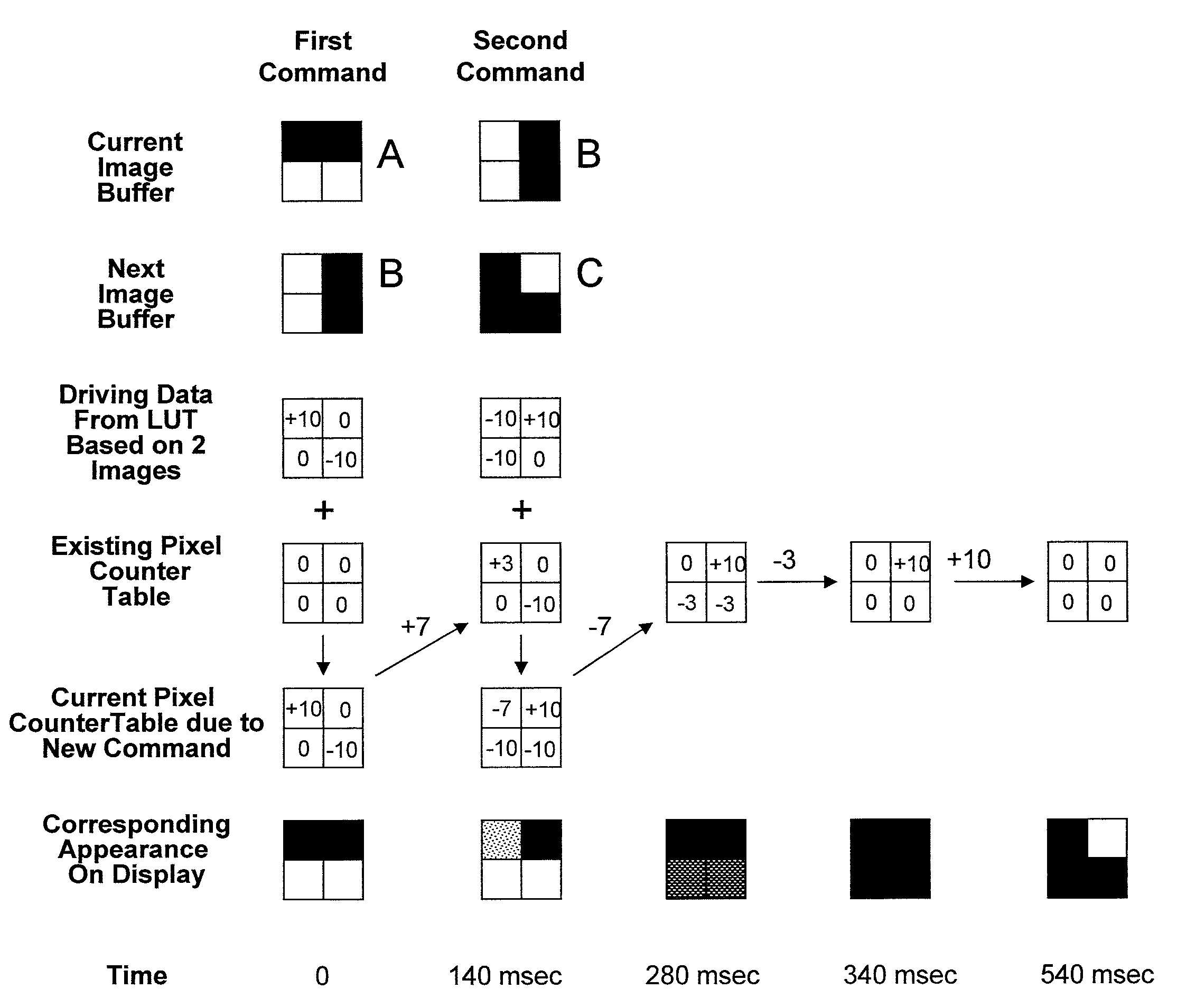
[0089]These three examples show the driving method of the present invention in which the initial command wishes to update image A to image B and the interrupting second command wishes to update to image C. The three examples are demonstrated in FIGS. 8, 9 and 10, respectively, all driven by the mono-polar waveforms of FIG. 4.

example 2

[0090]This example is summarized in FIG. 8.

[0091]The first command wishes to update image A to image B. The display controller compares the two images and based on the comparison finds in a look-up table the driving data with pixels A-D being, +10, 0, 0 and −10, respectively.

[0092]Since this is the first command, at the time when it is received, the existing pixel counter table has all pixels A-D being 0.

[0093]The driving data obtained are then added to the existing pixel counter table, resulting in a current pixel counter table, due to the new command, in which pixels A-D are +10, 0, 0 and −10, respectively.

[0094]In this example, after 7 frames in phase I (+7) are driven, a second command is received to update to image C. The display controller then compares images B and C and based on the comparison finds in the look-up table the driving data with pixels A-D being −10, +10, −10 and 0, respectively.

[0095]Since 7 frames in phase I (+7) have been driven, the existing pixel counter ta...


PUM


Abstract

The driving system and methods of the present invention enable interruption of updating images. The system and methods not only have the advantage that they can prevent overdriving of an electrophoretic display, but they also allow updating images in the highest speed possible.

Description

[0001]This application claims priority to U.S. Provisional Application No. 61 / 296,832, filed Jan. 20, 2010; the content of which is incorporated herein by reference in its entirety.BACKGROUND OF THE INVENTION[0002]An electrophoretic display (EPD) is a non-emissive device based on the electrophoresis phenomenon of charged pigment particles suspended in a solvent. The display usually comprises two plates with electrodes placed opposing each other and one of the electrodes is transparent. A suspension composed of a colored solvent and charged pigment particles dispersed therein is enclosed between the two plates. When a voltage difference is imposed between the two electrodes, the pigment particles migrate to one side or the other, causing either the color of the pigment particles or the color of the solvent to be seen, depending on the polarity of the voltage difference.[0003]In order to obtain a desired image, driving waveforms are required for an electrophoretic display. A driving w...

Claims


Application Information

Patent Timeline
Patent Type & Authority Patents(United States)
IPC IPC(8): G09G3/34
CPCG09G3/344G09G2320/0252G09G2340/16
Inventor LIN, CRAIG
Owner E INK CORPORATION
Why Eureka
Try Eureka