Imaging apparatus and imaging method

a technology of imaging apparatus and imaging method, which is applied in the direction of optical radiation measurement, interferometric spectrometry, instruments, etc., can solve the problems of inability to obtain satisfactory results and inability to obtain two-dimensional differential phase images, and achieve high resolution

Active Publication Date: 2013-10-15
CANON KK
View PDF13 Cites 25 Cited by
  • Summary
  • Abstract
  • Description
  • Claims
  • Application Information

AI Technical Summary

Benefits of technology

[0021]The present invention provides an imaging apparatus and an imaging method capable of performing analysis with a high resolution when a period of a Moiré due to Talbot interference is analyzed by using a wave number space.

Problems solved by technology

With this transform method, a two-dimensional differential phase image cannot be obtained.
In particular, when the phase is retrieved by the method of analyzing the period of the Moiré by using the wave number space, a satisfactory result may not be obtained depending on the combination of the first and second gratings.

Method used


Image

  • Imaging apparatus and imaging method
  • Imaging apparatus and imaging method
  • Imaging apparatus and imaging method

Examples


example 1

[0121]Example 1 will be described with reference to FIGS. 4A to 4D.

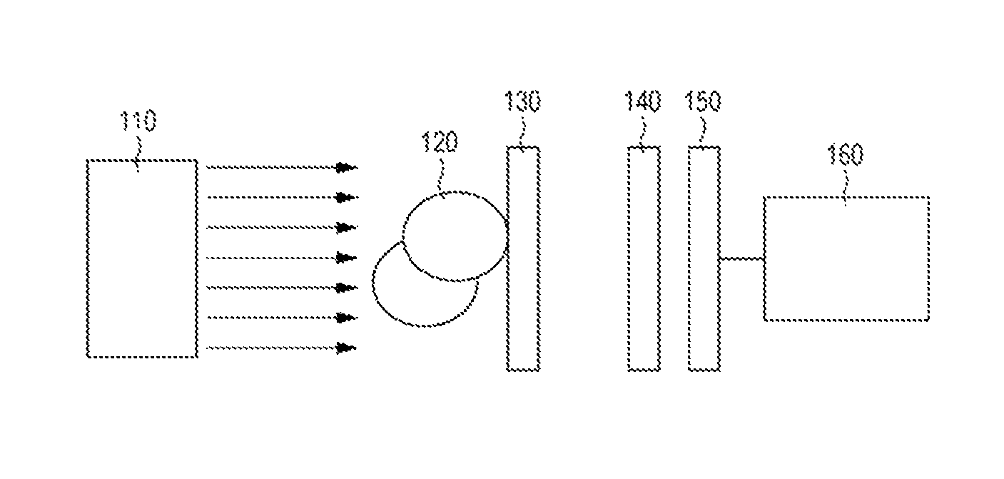
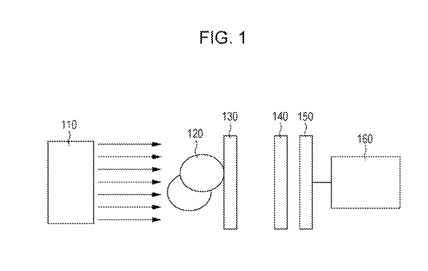
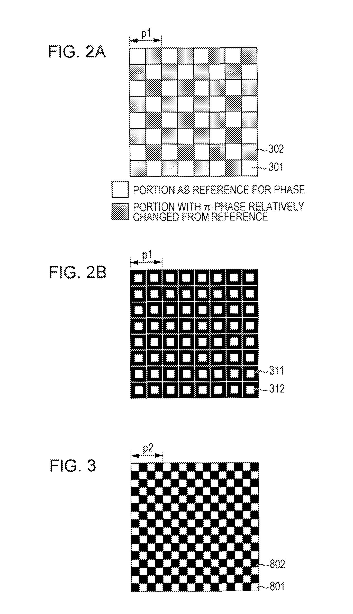
[0122]Example 1 has the same configuration as the configuration of the imaging apparatus described in the embodiment, and is different from the comparative example in the second grating. In particular, the imaging apparatus according to this example includes the X-ray source that emits parallel X-rays with 17.5 keV as the light source; the phase grating shown in FIG. 2A as the first grating; and the grating having the structure shown in FIG. 3 as the second grating. In addition, the imaging apparatus includes the detector and the arithmetic unit.

[0123]As described above, the second grating has the period p2 that is slightly different from the period p1 of the first grating. Due to the difference, the Moiré shown in FIG. 4A is formed. FIG. 4B illustrates the result obtained by performing the Fourier transform for the Moiré. FIG. 4C illustrates the intensity distribution of the X-rays along the axis A1 on the Moiré by ...

example 2

[0129]For Example 2, an imaging apparatus that uses a second grating including semi-transmissive portions will be described with reference to FIGS. 6A to 6D. The imaging apparatus of Example 2 has a structure similar to the structure of Example 1 except for a second grating.

[0130]FIG. 6A illustrates the second grating in this example. FIG. 6A schematically shows part of the shape of the second grating in an enlarged manner. Reference sign 1001 denotes transmissive portions, and 1002 denotes shielding portions for incident X-rays. In addition, the second grating used in this example includes semi-transmissive portions 1003 that transmit 50% of the incident X-rays. When the X-rays are transmitted through the semi-transmissive portions 1003 in this example, the intensity of the incident X-rays is halved, but the semi-transmissive portions 1003 are effective as long as the semi-transmissive portions 1003 transmit the X-rays more than the shielding portions 1002 do and shield the X-rays ...

example 3

[0136]In Example 3, an imaging apparatus that forms a self image that is different from the self image of the imaging apparatus according to Example 1 will be described with reference to FIGS. 8A and 8B, and 9A to 9D. The imaging apparatus of Example 3 has a structure similar to the structure of Example 1 except for first and second gratings.

[0137]FIG. 8A shows the first grating used in this example. It is to be noted that FIG. 8A shows part of the first grating in an enlarged manner.

[0138]FIG. 8A shows a grating (π / 2 grating) configured to shift the phase of X-rays transmitted through first regions 401 relative to the phase of the X-rays transmitted through second regions 402 by π / 2. Also, FIG. 8B shows a self image that is formed when the phase grating shown in FIG. 8A is used. The self image includes dark sections 411 and bright sections 412 that are arranged in a periodic checker board designed pattern with a period p1. This self image has a two-dimensional period.

[0139]FIG. 9A ...


PUM


Abstract

An imaging apparatus analyzes a periodic pattern of a Moiré due to Talbot interference by the Fourier transform method and forms an image. The imaging apparatus includes a first grating having a structure that transmits light beams from a beam source to refract or diffract the light beams and forms a self image based on a first periodic pattern by the Talbot interference at a predetermined position; a second grating that absorbs part of the first periodic pattern and causes a Moiré to be generated based on a second periodic pattern when the second grating is arranged at a position at which the self image is formed. All cross sections of the Moiré with axes in differential directions of a wavefront for the analysis by the Fourier transform method have a two-dimensional periodic structure in which periods of patterns in the second periodic pattern are the same.

Description

CROSS REFERENCE TO RELATED APPLICATIONS[0001]This application is a Continuation-in-part (CIP) of prior U.S. patent application Ser. No.: 12 / 842937 filed Jul. 23, 2010, which is a continuation of International Patent Application No. PCT / JP2009 / 068434 filed Oct. 27, 2009, the disclosures of which are hereby incorporated by reference herein in their entirety.BACKGROUND OF THE INVENTION[0002]1. Field of the Invention[0003]The present invention relates to imaging apparatuses and imaging methods, and more particularly relates to an imaging apparatus and an imaging method that forms an image of a subject by using Talbot interference.[0004]2. Description of the Related Art[0005]Imaging techniques that use interference of light with various wavelengths including visible light and X-rays have been known.[0006]Known one of such imaging methods may be a Talbot interference method.[0007]The Talbot interference method will be briefly described below. When a subject is irradiated with light, the p...

Claims


Application Information

Patent Timeline
Patent Type & Authority Patents(United States)
IPC IPC(8): G03H5/00
CPCG01N23/04G01N2223/401G01N23/041
Inventor OUCHI, CHIDANENAGAI, KENTARO
Owner CANON KK
Why Eureka
Try Eureka