Motion analyzing apparatus

a technology of motion analysis and apparatus, which is applied in the field of motion analysis apparatus, can solve the problems of large size of the apparatus, increased error included in the output of the sensor, and difficulty in handling the apparatus, and achieves the effect of convenient handling and sufficient accuracy

Inactive Publication Date: 2013-10-22
SEIKO EPSON CORP
View PDF6 Cites 53 Cited by
  • Summary
  • Abstract
  • Description
  • Claims
  • Application Information

AI Technical Summary

Benefits of technology

[0014]An advantage of some aspects of the invention is that it provides a motion analyzing apparatus that can be easily handled and provide analysis information with sufficient accuracy.
[0019]According to the above-described motion analyzing apparatus, the detection error of the sensor unit is estimated as a time function, and the m time integrals of the physical amount of the detection target is corrected by using the estimated time function of the error, whereby analysis information having sufficient accuracy can be generated. In addition, a sensor is used instead of an infrared camera, the configuration can be simplified, and the handling thereof is easy.
[0023]As above, by setting up the over-determined simultaneous equations by acquiring more data in the first period, the estimation accuracy of the time function of the detected error can be increased. In addition, for example, the over-determined simultaneous equations may be solved by using a least squares method.
[0025]By arranging a plurality of the first periods as above, the estimation accuracy of the time function of the detected error can be increased further.
[0027]In such a case, the estimation accuracy of the time function of the detected error for the second period as a target of the motion analysis can be further increased, and accordingly, the motion analysis information having higher accuracy can be generated.

Problems solved by technology

However, in such apparatuses, since an infrared camera used for photographing images is necessary, the size of the apparatuses is in consequence large, and, accordingly, there is a problem in that it is difficult to handle the apparatuses.
However, generally, an error other than a value to be observed is included in the output value of an inertial sensor.
In other words, in a motion analyzing apparatus using an inertial sensor, the characteristics of the sensor are not sufficient in practice, and in a case where the posture, the velocity, the position, and the like are calculated by performing an integration process for the output data of the inertial sensor, an error included in the output of the sensor noticeably increases through the integration process, whereby there is problem in that a sufficient analysis (measurement) capability is not acquired.

Method used


Image

  • Motion analyzing apparatus
  • Motion analyzing apparatus
  • Motion analyzing apparatus

Examples


Embodiment Construction

[0043]Hereinafter, a preferred embodiment of the invention will be described in detail with reference to the accompanying drawings. The embodiment described here is not for purposes of inappropriately limiting the content of the invention that is defined in the claims. In addition, not all the configurations described below are determined as essential constituent elements of the invention.

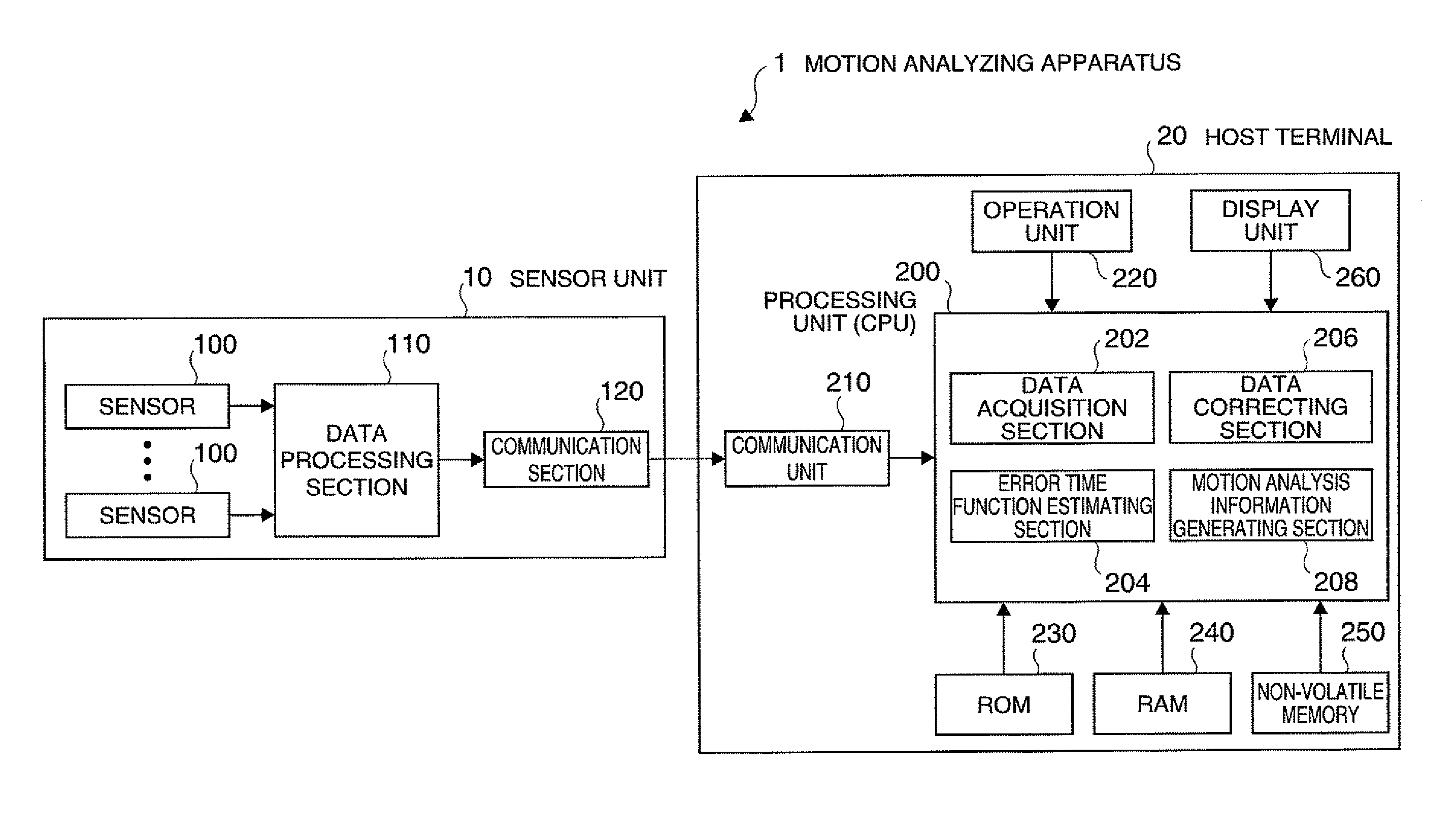
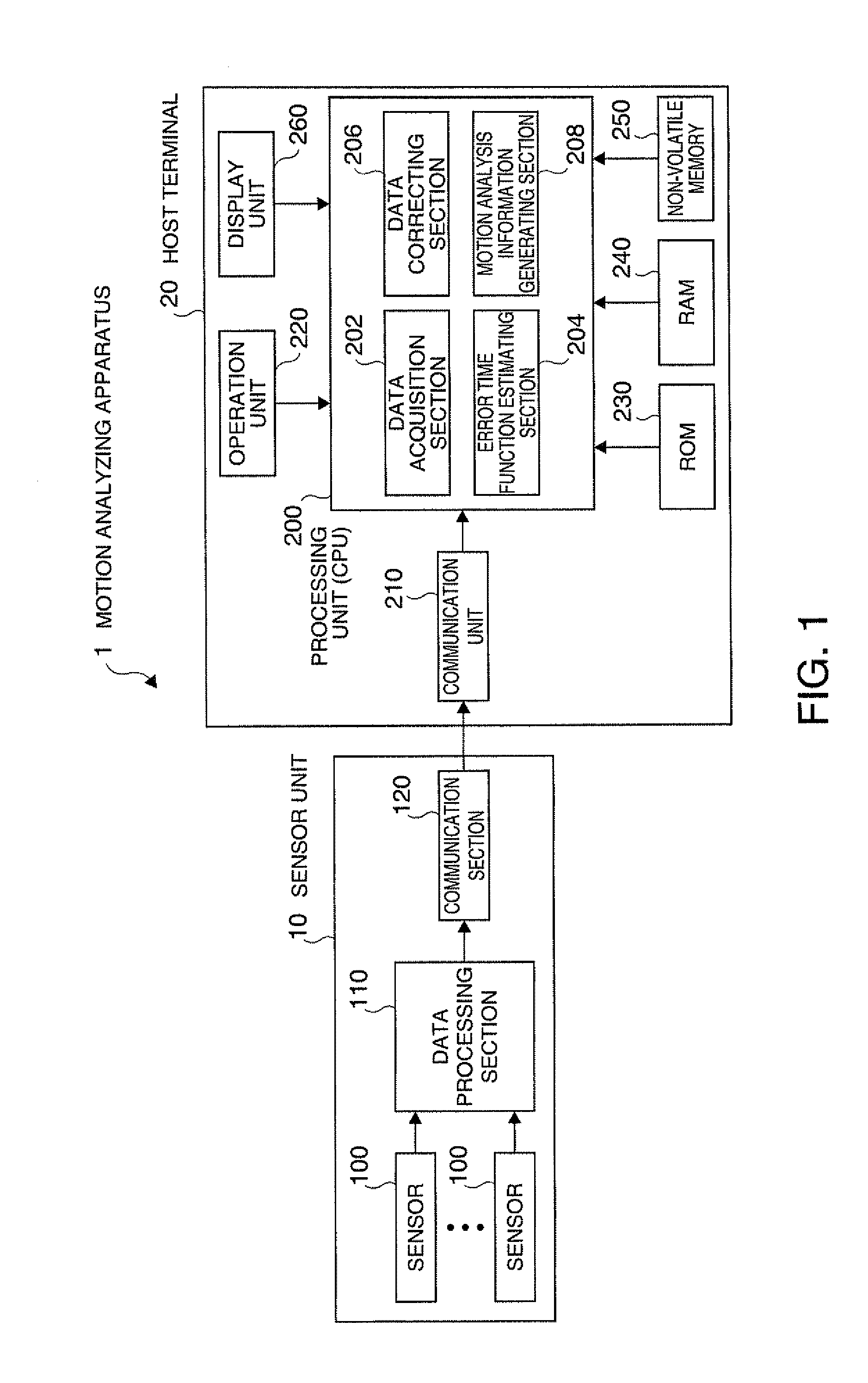
[0044]FIG. 1 is a diagram showing the configuration of a motion analyzing apparatus according to this embodiment.

[0045]The motion analyzing apparatus 1 according to this embodiment is configured so as to include one or a plurality of sensor units 10 and a host terminal 20 and analyzes the motion of a target object. The sensor unit 10 and the host terminal 20 are interconnected in a wired or wireless manner.

[0046]The sensor unit 10 is installed to a target object for motion analysis and performs a process of detecting a given physical amount. In this embodiment, the sensor unit 10 is configured so a...


PUM


Abstract

A sensor unit is installed to a target object and detects a given physical amount. A data acquisition unit acquires output data of the sensor unit in a period including a first period for which a real value of a value of m time integrals of the physical amount is known and a second period that is a target for motion analysis. An error time function estimating unit performs m time integrals of the output data of the sensor unit and estimates a time function of an error of a value of the physical amount detected by the sensor unit with respect to the real value of the value of the physical amount detected by the sensor unit based on a difference between a value of m time integrals of the output data and the real value for the first period.

Description

BACKGROUND[0001]1. Technical Field[0002]The present invention relates to a motion analyzing apparatus.[0003]2. Related Art[0004]In various fields, apparatuses that analyze the motion of a person or an object are necessary. For example, by analyzing the swing trajectory of a tennis racket or a golf club, the form of baseball pitching or batting, and the like and clarifying points to be improved based on the analysis result, game power can be improved.[0005]Currently, as practical motion analyzing apparatuses, apparatuses that analyze a motion by consecutively photographing a measurement object, to which a mark is attached, using an infrared camera or the like and calculating the motion trajectory of the mark using consecutive photographed images are generally used.[0006]JP-A-2004-24488 is an example of the related art.[0007]However, in such apparatuses, since an infrared camera used for photographing images is necessary, the size of the apparatuses is in consequence large, and, accor...

Claims


Application Information

Patent Timeline
Patent Type & Authority Patents(United States)
IPC IPC(8): G06K9/00A63B57/00A63B69/36A63B69/38
CPCA63B69/36G01P13/00A63B69/38G01P15/00G01P21/00
Inventor NAKAOKA, YASUSHI
Owner SEIKO EPSON CORP
Why Eureka
Try Eureka