Side offset charging handle

a charging handle and side offset technology, applied in the direction of breech mechanism, weapon components, weapon stance restrictions, etc., can solve the problem of difficult finger gripping of the lever b>12/b>, limited tactical stance,

Active Publication Date: 2013-10-29
SHARRON MATTHEW A
View PDF16 Cites 42 Cited by
  • Summary
  • Abstract
  • Description
  • Claims
  • Application Information

AI Technical Summary

Benefits of technology

[0008]Bearing in mind the problems and deficiencies of the prior art, it is therefore an object of the present invention to provide a sturdy charging handle which allows an operator to charge a firearm.

Problems solved by technology

The prior art charging handle does not permit the shooter to keep the weapon in close, restricts the tactical stance, and does not optimize the change of positioning time from holding the fore stock during firing to charging afterwards.
Moreover, lever 12 is difficult to grip with the fingers, especially when the operator is wearing gloves.

Method used


Image

  • Side offset charging handle
  • Side offset charging handle
  • Side offset charging handle

Examples


Embodiment Construction

)

[0040]In describing the preferred embodiment of the present invention, reference will be made herein to FIGS. 4-16 of the drawings in which like numerals refer to like features of the invention.

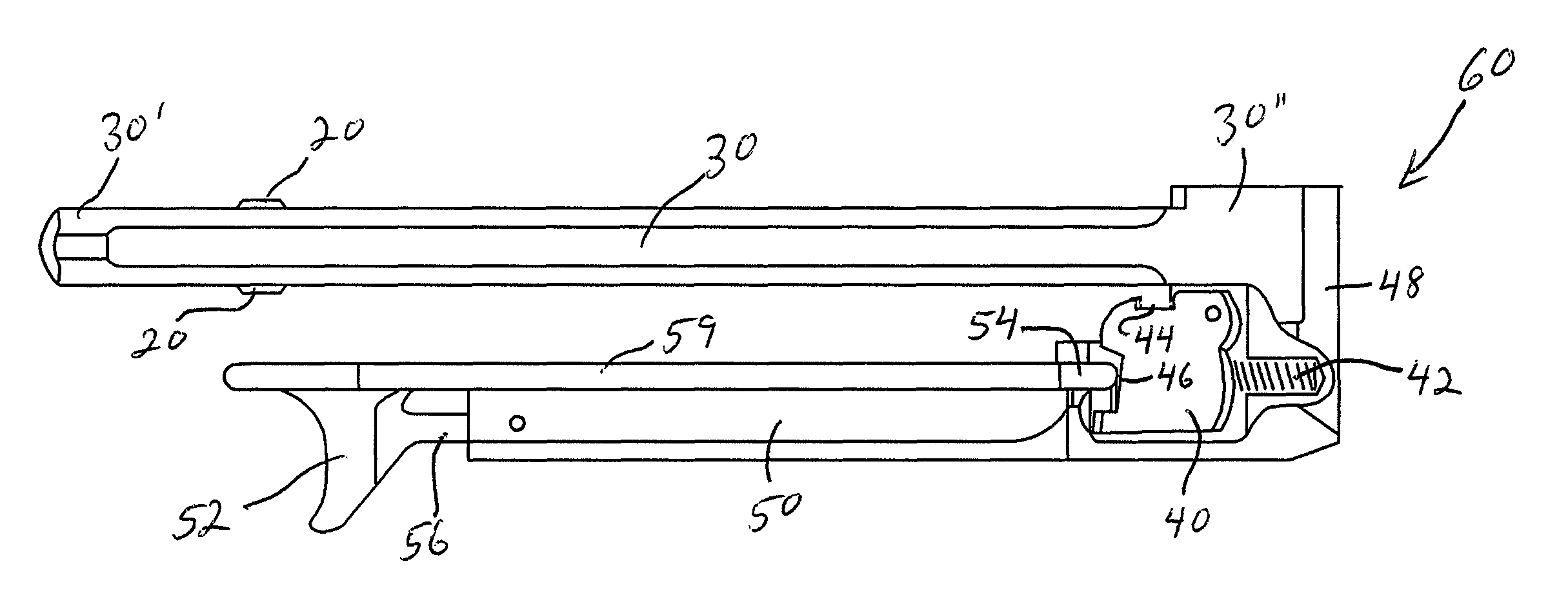
[0041]The charging handle 9 as shown in FIGS. 4-7 comprises a spar or generally elongated shaft member 30 having a forward end portion 30′ in the direction of the firearm barrel and a rearward end portion 30″ in the direction of the firearm stock. The elongated shaft member includes a groove 23 along the spar bottom which extends from about the forward end portion 30′ to the rearward end portion 30″. A bolt carrier contact lug 58 extends downward from the forward end portion 30′ of the spar 30. Spar protrusions 20 extend outward from the spar 30. Extending laterally from said rearward portion, the charging handle 9 also includes an offset arm 50 spaced from and extending parallel to at least a portion of the length of the elongated shaft member 30 in the direction of the firearm barrel. The ...


PUM


Abstract

A charging handle for a firearm having a barrel, a stock, a receiver, a receiver trigger and a bolt reciprocating within the receiver. The firearm may include a gas tube for directing powder gases to cause operation of the bolt within the receiver. The charging handle comprising a generally elongated spar having a forward end portion in the direction of the firearm barrel and a rearward end portion in the direction of the firearm stock. The charging handle includes a latch engaging the receiver to hold the charging handle in a forward most position and, extending laterally from said rearward portion, an offset arm extending at least a portion of the length of the elongated shaft member in the direction of the firearm barrel.

Description

BACKGROUND OF THE INVENTION[0001]1. Field of the Invention[0002]The present invention relates to charging handles for a firearm, and is particularly useful for rifles such as AR-15 / M16 / M4 / AR-10 type weapons.[0003]2. Description of Related Art[0004]Firearms, particularly of the automatic or semi-automatic type, may incorporate a charging handle which performs a variety of functions. FIG. 1 shows an exploded view of a charging handle 8 and bolt carrier 6 attached to a firearm 80. The firearm 80 includes a barrel 82, a fore stock 92, a butt stock 84, an upper receiver 86, a lower receiver 88, and a receiver trigger 90. The firearm may also include a removable magazine cartridge 5. A bolt 19 is engaged with the bolt carrier 6. In operation, the bolt carrier 6 reciprocates within the upper receiver 86. The firearm 80 includes a gas tube 25 extending from the barrel 82 to a bolt carrier 6 and an eyesight 39. The eyesight 39 has an internal chamber 37 in communication with one end of the g...

Claims


Application Information

Patent Timeline
Patent Type & Authority Patents(United States)
IPC IPC(8): F41A7/02
CPCF41A3/72F41A35/06
Inventor SHARRON, MATTHEW A.
Owner SHARRON MATTHEW A
Why Eureka
Try Eureka