Apparatus and method of controlling cutting blade travel through the use of etched features

a technology of etched features and apparatus, applied in the field of apparatus and method of controlling cutting blade travel through the use of etched features, to achieve the effect of facilitating the translation of the cutting blad

Active Publication Date: 2013-10-29
TYCO HEALTHCARE GRP LP
View PDF110 Cites 277 Cited by
  • Summary
  • Abstract
  • Description
  • Claims
  • Application Information

AI Technical Summary

Benefits of technology

[0008]The cutting blade is configured for selective translation within the curved blade channel and is formed by at least one of machining, photolithography and stamping. Proximal portions of a first sidewall are manufactured to include incident angles of less than five degrees that engage the cutting blade during translation thereof to direct the cutting blade towards a specific point of contact on the opposing sidewall of the curved blade channel. The specific point of contact on the opposing sidewall includes an incident angle of less than five degrees to further the cutting blade along the curved blade channel. One of the sidewalls is concave and the opposite sidewall is convex. The cutting blade is configured to engage and translate along the sidewalls in a substantially tangential manner. The cutting blade contacts the first sidewall of the cutting blade channel at an incident angle of less than five degrees and contacts the opposing sidewall of the cutting blade channel at an incident angle of less than five degrees. In one embodiment, the curved blade channel is manufactured by photolithography and the curved blade channel includes at least one etched feature that controls movement of the cutting blade along the curved blade channel. The etched feature(s) is disposed on the first sidewall and directs the cutting blade toward the specific point of contact on the opposing sidewall of the curved blade channel. The opposing sidewall includes one or more etched features that facilitate translation of the cutting blade along the curved blade channel in a substantially tangential manner.

Problems solved by technology

An endoscopic forceps that is configured for use with small cannulas (e.g., cannulas less than five millimeters) may present design challenges for a manufacturer of endoscopic instruments.

Method used


Image

  • Apparatus and method of controlling cutting blade travel through the use of etched features
  • Apparatus and method of controlling cutting blade travel through the use of etched features
  • Apparatus and method of controlling cutting blade travel through the use of etched features

Examples


Embodiment Construction

[0030]Detailed embodiments of the present disclosure are disclosed herein; however, the disclosed embodiments are merely examples of the disclosure, which may be embodied in various forms. Therefore, specific structural and functional details disclosed herein are not to be interpreted as limiting, but merely as a basis for the claims and as a representative basis for teaching one skilled in the art to variously employ the present disclosure in virtually any appropriately detailed structure.

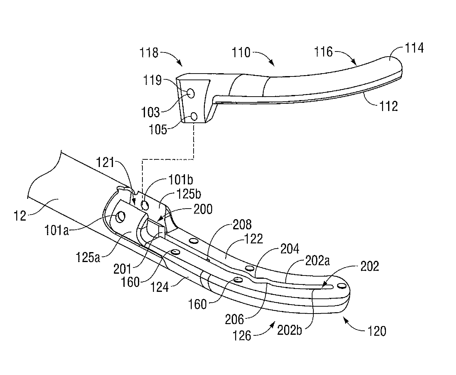
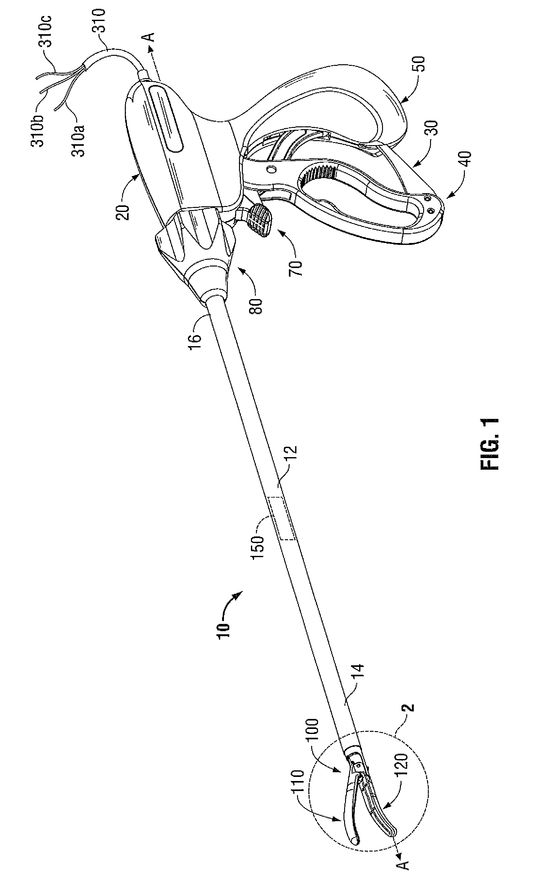
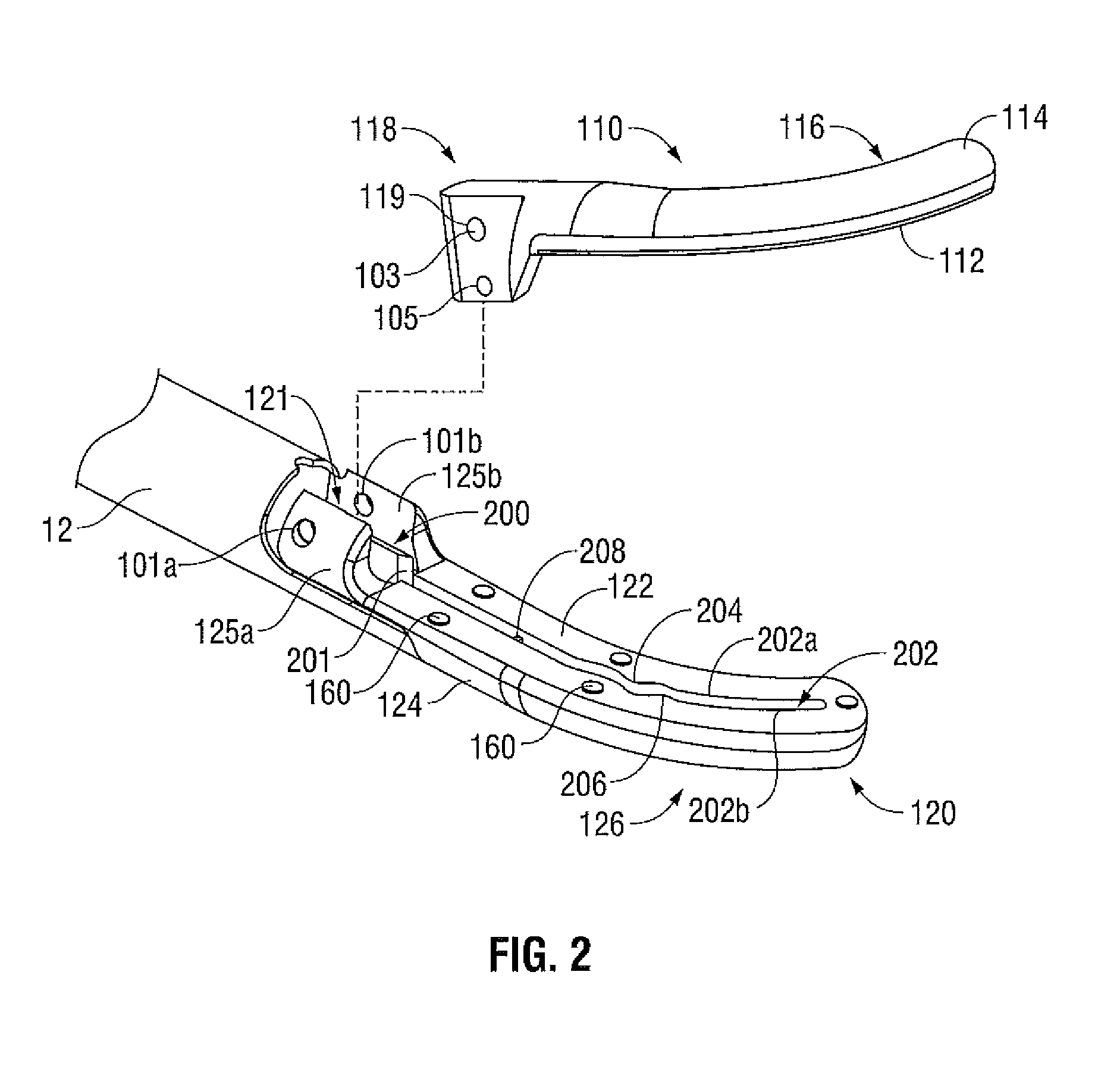
[0031]As noted above, it may prove useful to provide an electrosurgical apparatus that is suitable for use with various access ports, including but not limited to those that are greater than and / or less than five millimeters. With this purpose in mind, the present disclosure includes an electrosurgical forceps that includes a drive assembly operatively coupled to one or more jaw members associated with the end effector assembly of the electrosurgical forceps. The drive assembly is configured to mo...


PUM


Abstract

A forceps includes a housing including a shaft. The shaft includes an end effector assembly having a pair of curved jaw members. The jaw members include an electrically conductive surface and a curved blade channel having opposing sidewalls. A cutting blade is configured for translation within the blade channel. Proximal portions of a first sidewall include incident angles of less than five degrees that engage the cutting blade and direct the blade towards a specific point of contact on the opposing sidewall of the curved blade channel.

Description

BACKGROUND[0001]1. Technical Field[0002]The present disclosure relates to an apparatus and method of controlling cutting blade travel in a surgical instrument. More particularly, the present disclosure relates to an apparatus and method of controlling cutting blade travel through the use of etched features using photolithography.[0003]2. Background of Related Art[0004]Electrosurgical apparatuses (e.g., electrosurgical forceps) are well known in the medical arts and typically include a handle, a shaft and an end effector assembly operatively coupled to a distal end of the shaft that is configured to manipulate tissue (e.g., grasp and seal tissue). Electrosurgical forceps utilize both mechanical clamping action and electrical energy to effect hemostasis by heating the tissue and blood vessels to coagulate, cauterize, fuse, seal, cut, desiccate, and / or fulgurate tissue.[0005]As an alternative to open electrosurgical forceps for use with open surgical procedures, many modern surgeons us...

Claims


Application Information

Patent Timeline
Patent Type & Authority Patents(United States)
IPC IPC(8): A61B18/14
CPCA61B18/1445A61B2017/2945A61B2018/00404A61B2018/00601A61B2018/0063A61B2018/1412A61B2018/1432A61B2018/1455
Inventor BRANDT, KIM V.AQUINO, ALLAN G.
Owner TYCO HEALTHCARE GRP LP
Why Eureka
Try Eureka