Bearing assembly

a technology of bearings and components, applied in the direction of bearing units, rigid supports, mechanical equipment, etc., can solve the problems of electric motors that cannot be fixed, can be damaged and eventually totally immobilized, and cannot be moved,

Active Publication Date: 2013-10-29
ABB (SCHWEIZ) AG
View PDF10 Cites 0 Cited by
  • Summary
  • Abstract
  • Description
  • Claims
  • Application Information

AI Technical Summary

Benefits of technology

[0005]One aim of the present invention is thus to provide a bearing assembly making it possible for an electrical motor with a broken down bearing to continue functioning a limited time period, which arrangement also provides a safety function to prevent or minimise damage on the electrical motor.
[0006]Another aim of the invention is to provide an electrical motor with low friction losses and a maintenance free solution for a grease sealing.
[0007]According to one aspect of the invention there is provided a bearing assembly for an electrical motor, the bearing assembly comprising a shaft, a housing, and a main bearing between the shaft and the housing, wherein the shaft is surrounded by a rigid sleeve that functions as an auxiliary bearing in case of a breakdown of the main bearing, the clearance between the sleeve and the shaft being smaller than the air-gap between a stator and a rotor of the motor. The auxiliary bearing prevents the collision of the rotor and the stator of the motor in case of a failure of the main bearing.

Problems solved by technology

When a bearing breaks down, the electrical motor can be damaged and eventually totally immobilized.
In e.g. railway traction motor applications this means a stand still of the train and expensive measures to get a repair of the motor done either in situ or in a repair shop, in which case the locomotive must be transported by a service train or lifted off the track.
These measures are clearly both expensive and time consuming.
A lip seal is a wearing part and a labyrinth seal is a complicated component with high friction losses.

Method used


Image

  • Bearing assembly
  • Bearing assembly

Examples


Embodiment Construction

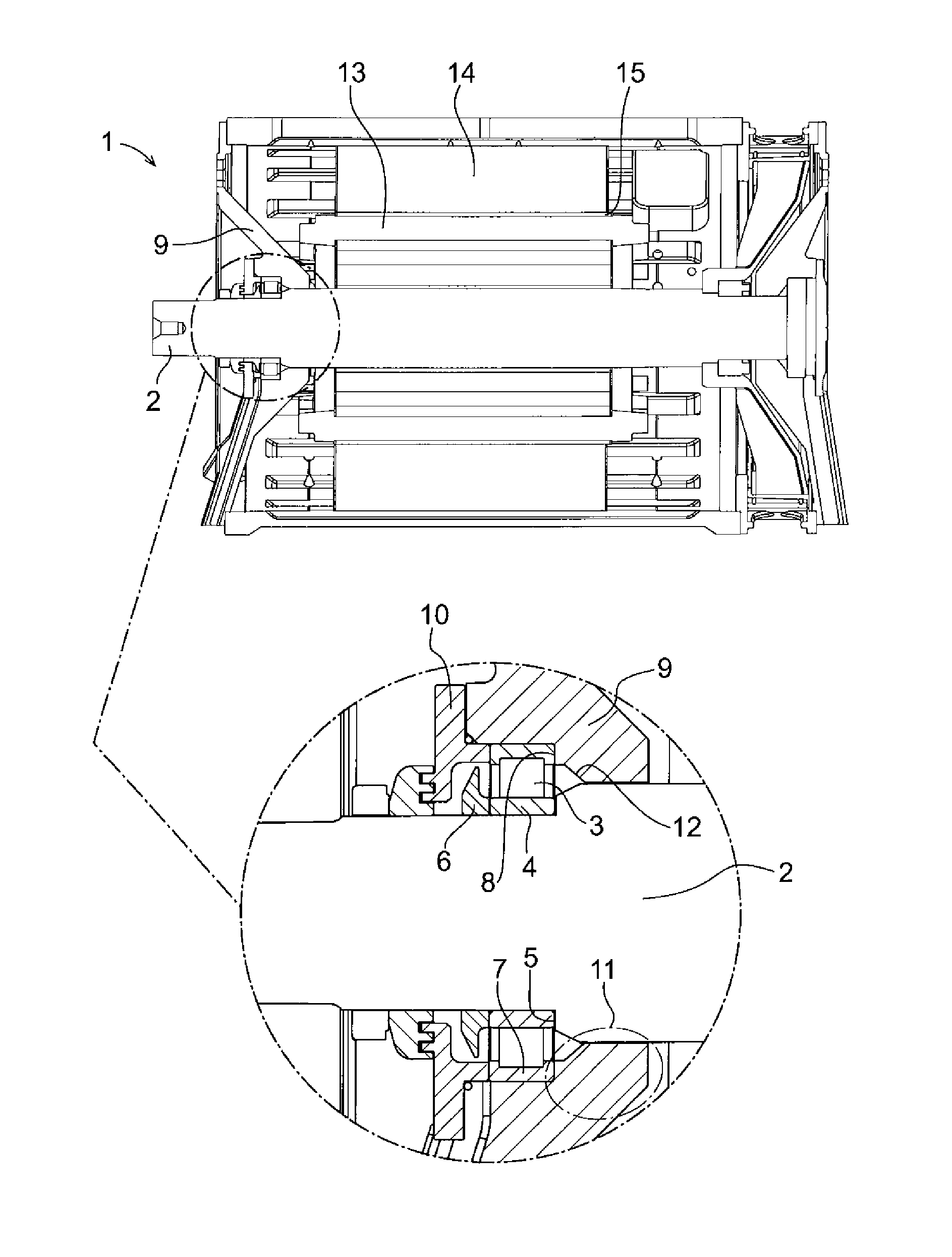
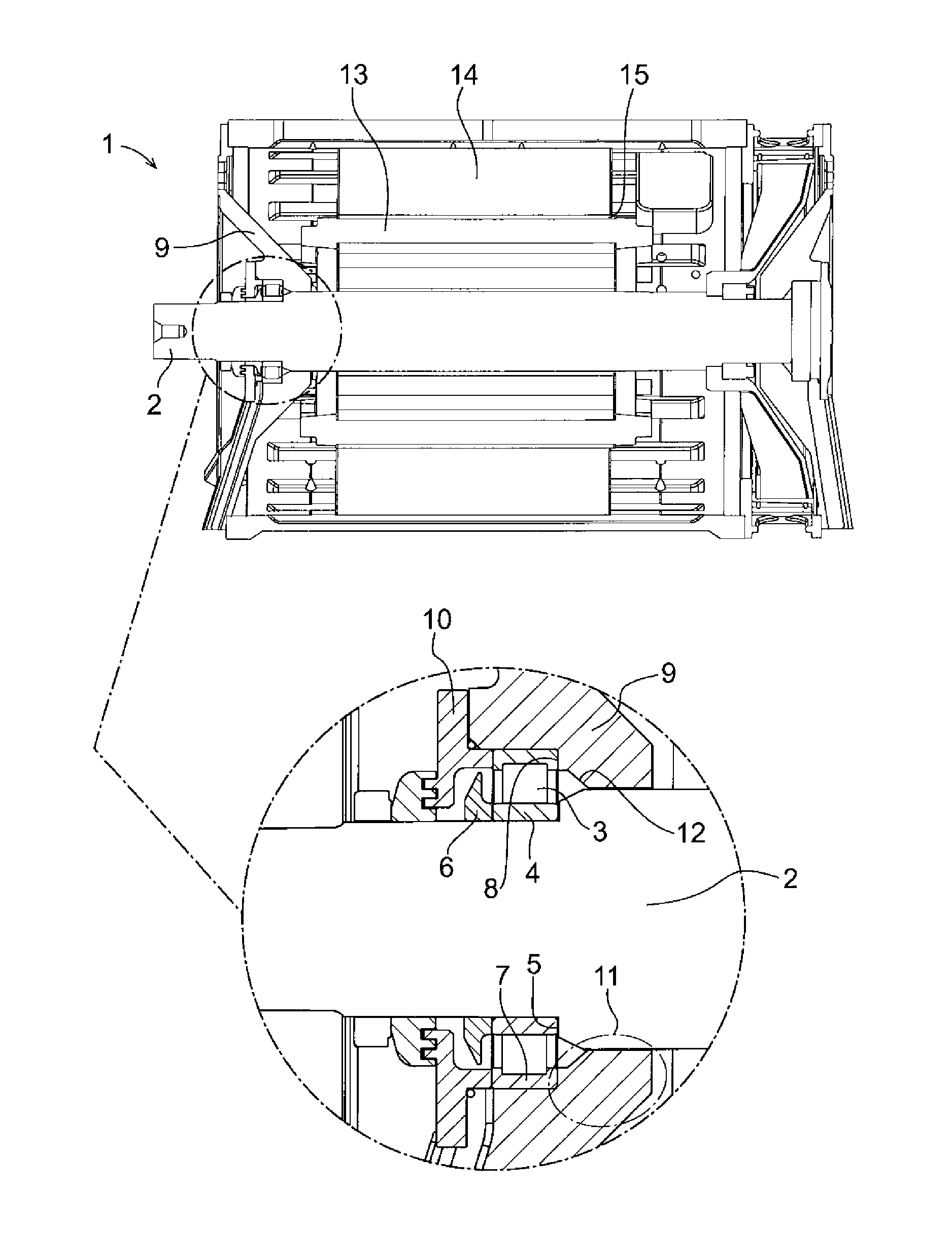
[0018]FIG. 1 shows a traction motor 1 comprising an end shield 9 supporting a shaft 2 on which an inner race 4 of a main bearing 3 is arranged. The inner race 4 is locked axially inwards against a first bearing seat 5 on the shaft 2 by an inner locking ring 6. A rotor 13 is arranged on the motor shaft 2.

[0019]An outer race 7 of the main bearing 3 is locked axially inwards against a second bearing seat 8 provided in the end shield 9 by an outer locking ring 10. The end shield 9 is a part of the motor housing and comprises a sleeve 11 that extends inwards from the second bearing seat 8. At the bearing seat 8 the sleeve 11 has a considerably larger inner diameter than that of the shaft 2, but the sleeve 11 tapers radial inwards to conform to the shaft 2 along some distance with only a slightly larger inner diameter such that the clearance between the sleeve 11 and the shaft 2 is about 0.05 to 0.6 mm. The clearance between the sleeve 11 and the shaft 2 is smaller than the air-gap 15 bet...


PUM


Abstract

A bearing assembly for an electrical motor, including a shaft, a housing, and a main bearing between the shaft and the housing, the shaft being surrounded by a rigid sleeve for functioning as an auxiliary bearing in case of a breakdown of the main bearing and as a grease sealing under normal operation.

Description

CROSS-REFERENCE TO RELATED APPLICATIONS[0001]The present application is a continuation of pending International patent application PCT / EP2009 / 053569 filed on Mar. 26, 2009 which designates the United States and the content of which is incorporated herein by reference.FIELD OF THE INVENTION[0002]The present invention relates to a bearing assembly for an electrical motor and to an electrical motor comprising such a bearing assembly.BACKGROUND OF THE INVENTION[0003]A shaft of an electrical motor is mounted on bearings at both of its ends. The bearings are typically supported by the end shields of the motor housing. When a bearing breaks down, the electrical motor can be damaged and eventually totally immobilized. In e.g. railway traction motor applications this means a stand still of the train and expensive measures to get a repair of the motor done either in situ or in a repair shop, in which case the locomotive must be transported by a service train or lifted off the track. These mea...

Claims


Application Information

Patent Timeline
Patent Type & Authority Patents(United States)
IPC IPC(8): H02K7/08
CPCF16C19/522F16C21/00F16C33/80F16C39/02F16J15/164H02K5/124H02K5/1672H02K5/1732H02K7/083F16C2380/26F16C2326/10
Inventor ISBERG, PETERLINDBERG, PER-OLOF
Owner ABB (SCHWEIZ) AG
Why Eureka
Try Eureka