Electro-optical distance meter

a technology of optical distance meter and optical plate, which is applied in the direction of distance measurement, height/levelling measurement, instruments, etc., can solve the problems of motion slowed down at low temperature, not only the time of distance measurement, and the temperature phase drift of electrical components can be reduced, so as to reduce the temperature phase drift of electrical components and reduce the cost

Active Publication Date: 2013-10-29
KK TOPCON
View PDF6 Cites 1 Cited by
  • Summary
  • Abstract
  • Description
  • Claims
  • Application Information

AI Technical Summary

Benefits of technology

[0016]By the electro-optical distance meter according to the first aspect of the present invention, because the initial phases of the respective intermediate frequency signals according to the distance measuring optical path and reference light paths are simultaneously determined without using a shutter for switching between the distance measuring light and reference light and also without switching modulation frequencies, a distance measurement can be performed more speedily than conventionally performed. Moreover, a cost reduction by omitting a shutter is enabled. Further, according to the present invention, because a simultaneous measurement of the measuring distance and reference distances is enabled, the temperature phase drift cancels out, and the temperature phase drift of electrical components can be reduced. Therefore, conventionally, light-emitting elements under a continuous distance measurement had been kept powered on in order to reduce the temperature phase drift of the electrical components, but the power of the light-emitting elements can be turned on and off at each measurement in the present invention, so that power saving can be realized.
[0017]By the second aspect of the present invention, further, the respective intermediate frequency signals have frequencies which are integral multiples of the lowest frequency, and the respective intermediate frequency signals are separated by a digital band-pass filter, and thus the four frequencies can be separated reliably to improve measurement accuracy.

Problems solved by technology

However, because a shutter movement is involved, there have been drawbacks that not only does the distance measurement take time, but also the motion is slowed down at low temperature.

Method used


Image

  • Electro-optical distance meter
  • Electro-optical distance meter
  • Electro-optical distance meter

Examples


Embodiment Construction

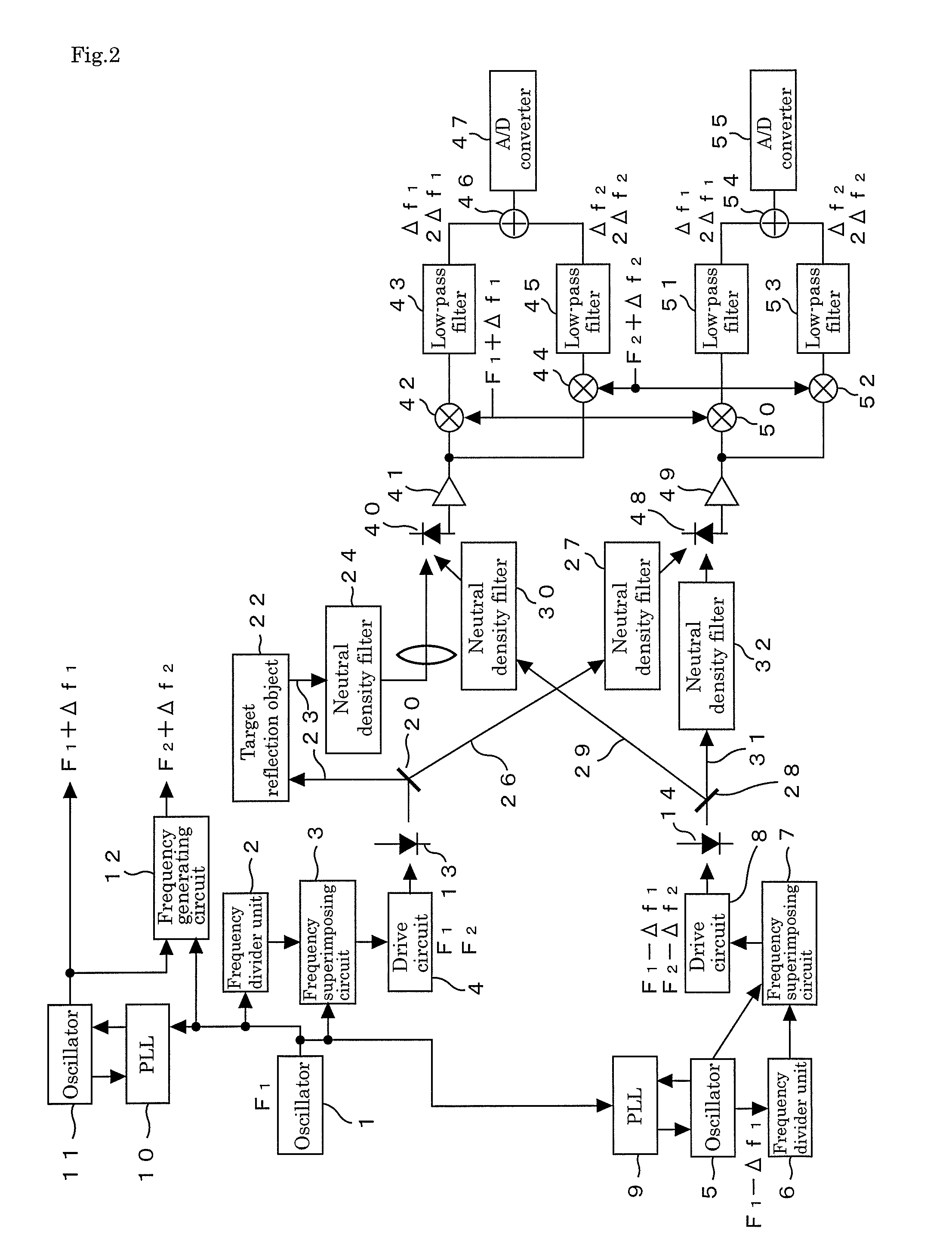
[0027]Hereinafter, an embodiment of an electro-optical distance meter of the present invention will be described in detail based on FIG. 1 to FIG. 3.

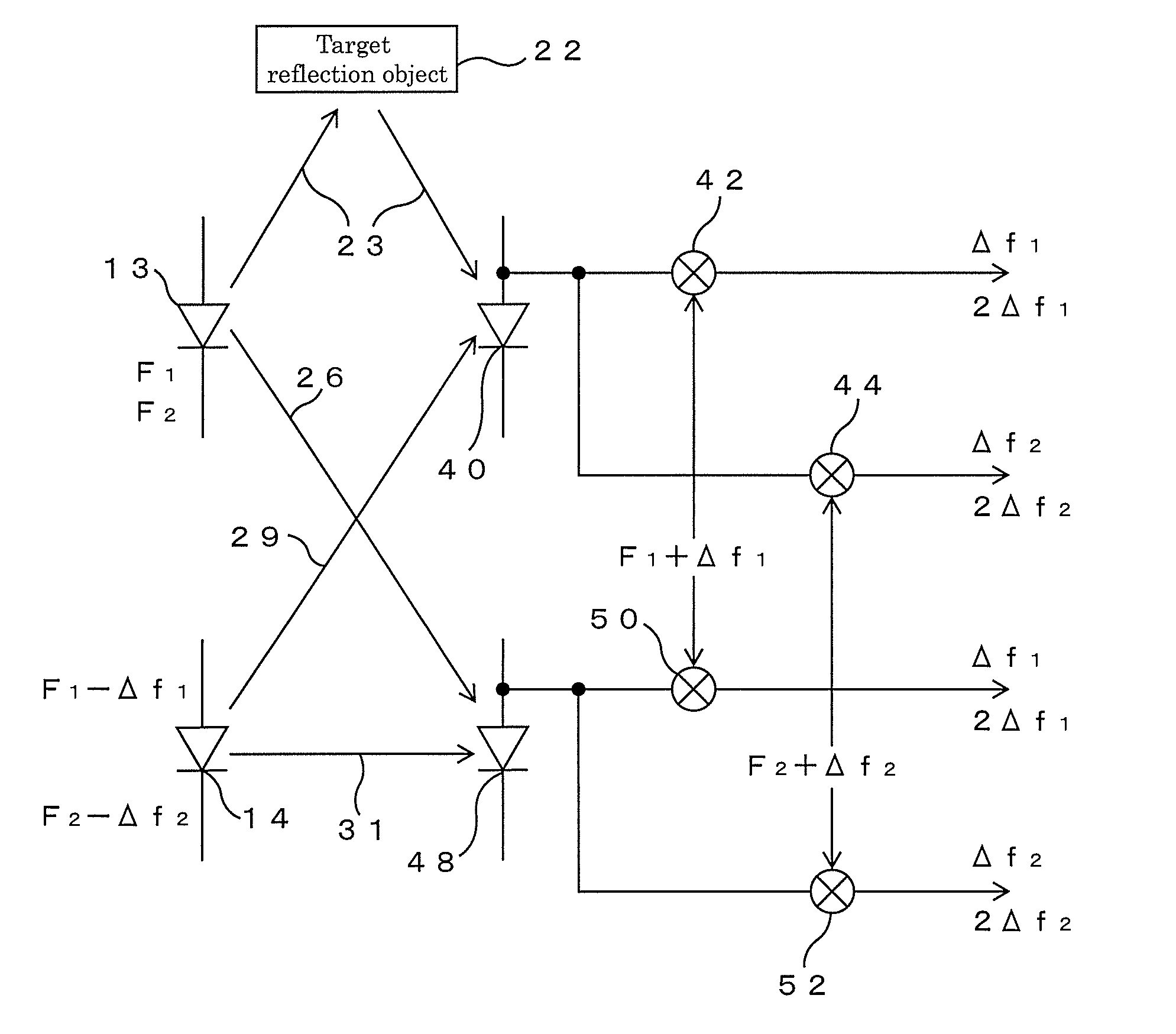
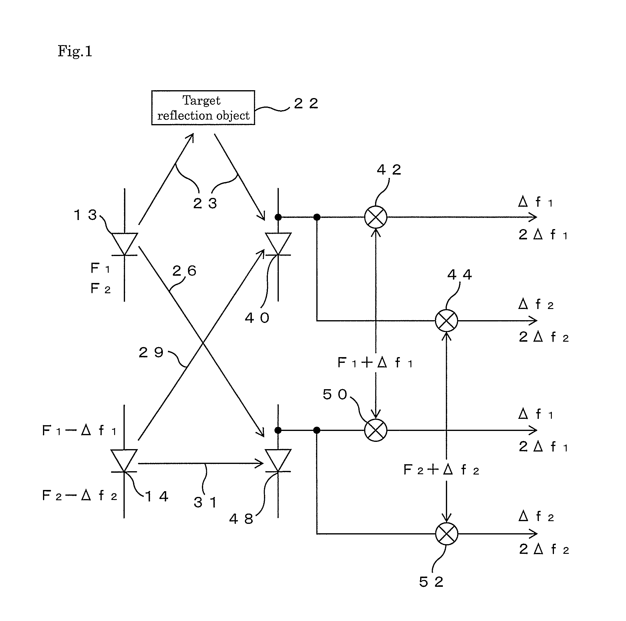
[0028]First, the main part of this electro-optical distance meter will be described based on FIG. 1. This electro-optical distance meter includes two light-emitting elements 13 and 14 such as laser diodes, emits light modulated with frequencies F1 and F2 (hereinafter, referred to as main modulation frequencies) from the first light-emitting element 13, and emits from the second light-emitting element 14 light modulated with frequencies F1−Δf1 and F2−Δf2 (hereinafter, referred to as adjacent modulation frequencies) close to the main modulation frequencies F1 and F2, respectively. The light emitted from the first light-emitting element 13 is split into two parts, one of these is as a distance measuring light made incident onto a first light receiving element 40 through a distance measuring optical path 23 for traveling to and from a targe...


PUM


Abstract

[Problem] To provide an electro-optical distance meter in which the measurement time is reduced, and a temperature phase drift of electrical components is reduced.[Solution Means] An electro-optical distance meter includes a first light-emitting element (13) which emits light modulated with a plurality of main modulation frequencies (F1 and F2), a second light-emitting element (14) which emits light modulated with a plurality of adjacent modulation frequencies (F1−Δf1 and F2−Δf2) close to the main modulation frequencies, respectively, first and second light receiving elements (40 and 48) which receive light emitted from both light-emitting elements, a first frequency converter group (42, 44) connected to the first light receiving element, and a second frequency converter group (50, 52) connected to the second light receiving element. The light emitted from the first light-emitting element is split into two parts, one of these is made incident onto the first light receiving element through a distance measuring optical path (23) for traveling to and from a target reflection object (22), and the other is made incident onto the second light receiving element through a first reference optical path (26), and the light emitted from the second light-emitting element is split into two parts, one of these is made incident onto the second light receiving element through a second reference optical path (31), and the other is made incident onto the first light receiving element through a third reference optical path (29).

Description

TECHNICAL FIELD[0001]The present invention relates to an electro-optical distance meter, and more particularly, to an electro-optical distance meter from which a shutter for switching light emitted from a light-emitting element into a distance measuring optical path (external optical path) and into a reference optical path (internal optical path) is omitted.BACKGROUND ART[0002]In a conventional electro-optical distance meter, errors unique to the electro-optical distance meter have been corrected by measuring the distance by alternately switching, by moving a shutter, light emitted from a light-emitting element into a distance measuring optical path for traveling to and from a target reflection object (a target, reflective sheet, or non-prism object) and into a reference optical path directly heading for a light receiving element from a light source. However, because a shutter movement is involved, there have been drawbacks that not only does the distance measurement take time, but ...

Claims


Application Information

Patent Timeline
Patent Type & Authority Patents(United States)
IPC IPC(8): G01C3/08
CPCG01S17/36
Inventor AOKI, YASUTOSHI
Owner KK TOPCON
Why Eureka
Try Eureka